
|
|
My antique radio restoration logs
The RCA R-28-P is a 5-tube AC non-AVC superhet circuit radio. It receives the standard broadcast band and one short wave band (police). The circuit is somewhat unusual, in that it has an RF amplifier stage but no IF amplifier stage. This radio had seen extensive servicing in the past. A block capacitor (C22 and 23) had been removed as well as the original can type filter capacitor on top (C21). A dual can type capacitor had been installed in place of C21 and one tubular filter cap tacked in below. Only one of the original wax-paper capacitors had been replaced. The line cord, the volume control, and several resistors had been replaced.
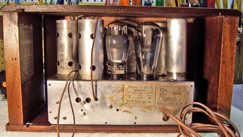
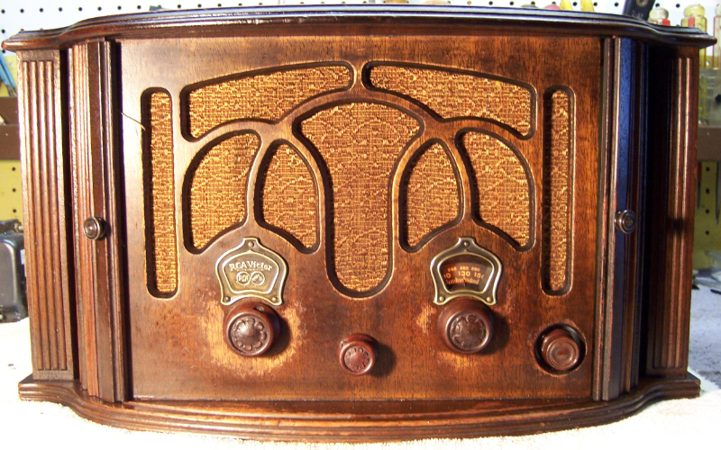
This same chassis is used in several RCA and GE radios. My example was installed in a small table radio cabinet with unique tambour doors that completely hide the front of the radio when closed.
I decided to try and restore as much of the original top and bottom chassis appearance if possible. This meant finding a way to replace the missing block capacitor C22/23 and finding a way to restuff the original RCA "chunk of tar" capacitors.
The schematic for the RCA R-28-P can be found on Nostalgia Air. Any part numbers will refer to numbers on that schematic.
My usual restoration procedure is to first make a complete survey of the condition of all components. The survey results guide my restoration strategy. If major and unique components are defective and cannot be restored, I may elect to sell the radio rather than restore it. I assume that all paper and electrolytic capacitors are leaky and thus should be replaced (I always "restuff" the original containers if possible).
The volume control R11 had been replaced. The switch worked, but the control was bad. It was a 3K control, probably wire wound, with a reverse taper and a fixed maximum resistance - very difficult to replace!
The power transformer, speaker field, speaker cone, and output transformer were OK (the cone had been patched once).
All the RF and oscillator coils as well as the IF transformer were OK..
One chassis mounted filter capacitor (C21) had been removed and replaced by a double capacitor of similar size. The two unit filter block under the chassis (C22/23) had been removed. A tubular filter had been installed.
The type 80 rectifier tube was OK but was the wrong type (tubular). All the tubes tested good.
The AC line cord was bad and was not original.
One knob was not the correct type - a Philco bakelite type was installed for the band switch knob.
7 resistors were out of tolerance by 33% to 44%. Any resistors within 20% were left in place. All resistors were originally dogbone types.
A defective Candohm type strip resistor had been soldered to the chassis and its lugs used for tie points (the dual filter block C22/23 originally provided this function, but it had been removed). Several non-original resistors had been installed, including one 10 watt wire wound in place of R9.
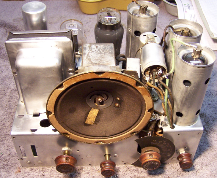
The chassis is very compact and there is really no way to access many of the components without removing others for access. Here is what the chassis looked like before the start of restoration:
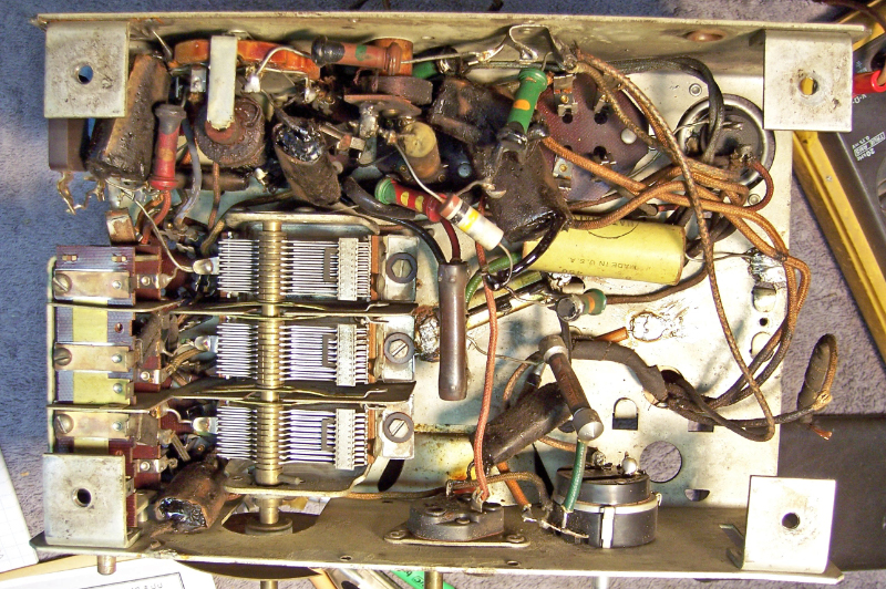
In order to gain access to the capacitors and resistors that needed replacement, I first removed the tuning capacitor, the volume control, the speaker (chassis top), the filter capacitors, the detector plate choke, and the antenna and RF coils (top of chassis). Next, all non-original parts below chassis were removed after taking careful notes.
All paper capacitors were rebuilt using modern 630 volt film capacitors in order to maintain the original under-chassis appearance. I came up with a way to restuff (more correctly to reproduce) these RCA capacitors that look like a block of tar. See Restuffing Early 1930's RCA Paper Capacitors.
The can type electrolytic capacitor which replaced C21 was rebuilt in its original can. The replacement had two lugs. I cut one off to make it more like the original.
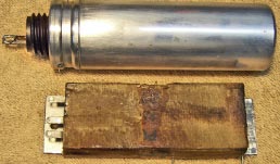
The missing block capacitor C22/23 was constructed from a dud block capacitor (I NEVER throw these away). The original contents were first removed. A metal mounting bracket was inserted so it could be bolted to the under side of the chassis. Three ground lugs were attached to one end of the case and connected to two 4mfd 450 volt electrolytics, with the center lug acting as a common ground (this is what was shown in RCA's wiring diagram for the radio). I was not successful in finding a photo of the actual capacitor, so I used the wiring diagram as my reference. The capacitor was then sealed up with rosin. Here are the restuffed or reproduced filter capacitors:
All the mica capacitors were left alone. Any of these that could be tested by lifting one lead (in the process of replacing another part) were tested. All that I tested were good.
All original resistors more than 20% out of tolerance were replaced. I used dogbone type resistors as were used originally. I picked out NOS and used dogbone resistors that had drifted to the correct needed resistance and then repainted them to match the original resistor's color codes. The replacements may continue to drift, as would most new carbon composition type resistors. But to me, maintaining the original look is more important than long term reliability of the radio.
 |
Here are the replacement dog-bone resistors, ready for installation in the radio. All have been repainted using hobby paint. The 14K (top right) was specified as 3 watt. I was unable to find a suitable dogbone in that size and wattage, so I painted a 15K 3 watt wire-wound! |
The original AC on-off switch and volume control had been replaced, but both the switch and the control were bad. The original was a 3K wire wound control with a reverse taper and a 100 ohm fixed segment. These are very difficult to replace. I installed a 10K (which measured 12K) linear taper control and placed a 3.9K 1/2 watt resistor in parallel and a 100 ohm 1/4 watt in series. These two resistors were placed in spaghetti tubing and located on the bottom of the control so as not to be visible. It worked, but the result was predictable: no reception until the control is at about 80% of rotation, then rapid change in volume. I will continue to look for a more appropriate control.
Once the radio was reassembled and tubes installed, power was brought up slowly using a variac. AC power was monitored using a watt meter, and a DVM monitored the B+. The radio came alive immediately and worked. Once at full power, voltage measurements were taken.
The set was aligned - no surprises. It picked up lots of stations using my basement 50' antenna. It picked up a few stations at the high end of the "police" band (there are no adjustments for this band).