Silvertone Model 1942 Restoration

|
The Silvertone 1942 (later version) from about 1936 is
a large 8 tube superhet tombstone radio that receives the broadcast band
and two short wave bands. It has a large speaker and push-pull
outputs. It also has a two-position switchable bandwidth IF stage that acts as a
tone control (it also has a separate normal tone control). The set
has a tuned pre-selector on the broadcast band, but has no RF amplifier
stage. The set
is unusual in that it uses metal-glass tubes, an early and short lived
competitor to RCA's metal tubes! It appears to have
been made by Colonial Radio, and the build quality is quite high.
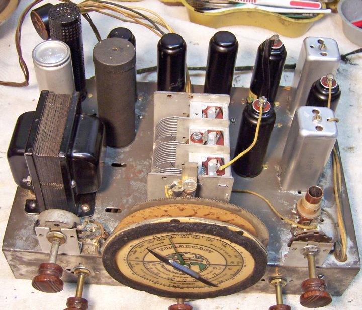
The radio had seen NO servicing that I could find - all the original
parts were still in place, even the power cord. I decided to try
to maintain the original above and below chassis appearance to the extent
possible. The schematic for this radio can be found on-line at Nostalgia
Air. |
My
antique radio restoration logs
Condition As Found
This radio was purchased on eBay. Unfortunately the
cabinet has been stripped of its original
finish. The grille cloth also MAY have been replaced. The knobs were
original. The radio was sold as working on the broadcast band with
scratchy controls (the seller did not know what the controls did!) There
was no shipping damage.
There was no signs of electrical restoration or even repairs! I always avoid knowingly purchasing a radio that has been
restored by a collector, as many take shortcuts such as removing the original capacitors and filters. When tested, the radio actually did work as stated, so all major
parts should be OK.
Previous Repairs
-
The 5Z4MG rectifier had been replaced by a 5Y3GT. All
the rest were likely the original Silvertone branded metal-glass tubes with
similar date codes! The 6E5 eye tube was also branded Silvertone, but
may have been a replacement.
-
All the original resistors were still in place.
-
All the original capacitors were still in place, including
the filter capacitors (which still had liquid inside and actually worked!)
-
The AC plug had likely been replaced.
-
Even the line cord was original, but in
poor shape.
Survey
My usual restoration procedure is to first make a complete
survey of the condition of all components. The survey results guide my
restoration strategy. If major and unique components are defective or
missing and
cannot be restored or replaced, I may elect to sell the radio rather than restore it.
I always assume that all paper and electrolytic capacitors are leaky and thus should be
replaced (I always "restuff" the original containers if possible).
Any mica capacitors are assumed OK until testing proves otherwise. Since
the radio actually worked, at least on the broadcast band, no major components were defective (RF coils, chokes,
transformers, RFCs,
etc.)
-
One chassis bolt was missing, along with its washer and rubber centering
bushing
-
A metal disc that fits underneath one of the chassis washers was missing.
-
All the knobs were on the wrong shafts! No wonder the seller could not
figure out what the controls did!
-
Several of the original Silvertone metal-glass tubes were weak, but likely
usable (the radio did work before restoration).
-
The eye tube was weak but usable.
-
Almost all of the dogbone type resistors were out of tolerance, some as high
as 100%.
-
The pilot lamp was good.
-
A three amp fuse was installed. The fuse holder ends were almost ready
to break off.
Repairs
All tubes were removed. The tuning capacitor and dial
assembly was removed for cleaning and access to other parts on
top. At this point I made BEFORE photos of the chassis bottom. I use these photos to ensure that replacement parts and
wiring are placed as close as possible to their original positions. Some
radios are subject to problems (such as oscillation) if wiring is re-routed or
lead dress is not the same as the original..
The top and sides of the chassis was cleaned with GoJo hand cleaner and 00 steel
wool. Since this process may leave small steel wool fragments that can cause
problems later, I follow up with a thorough vacuuming and go over everything
with a small magnet and masking tape to pick up any stray fragments.
The power cord was simply shortened to eliminate several unsafe or broken
areas. A more suitable old-style bakelite plug was installed. Some
of the outer cloth braid is missing, but the inner conductors are now safe to
use.
New tuning capacitor grommets were installed. I used type GLg-Tuner
available from Renovated
Radios.
The fuse holder ends were strengthened using solder. A 1-amp fast blow
fuse was installed in the holder.
Resistors and Capacitors
All of the original capacitors were restuffed using new 630 volt film
capacitors. Most all were branded Sprague, with a few CD "Tiger"
brands. Here is the process I use
when restuffing capacitors. In order to maintain the underside chassis
appearance, the out-of-tolerance dogbone resistors were replaced with the same
or similar types. I maintain a collection of NOS and used dogbone
resistors. Of course, most of these are also out of tolerance! So I
select a resistor from my stocks that has drifted to within 15-20% of the needed
value, and then repaint it to the needed value using hobby paints. In a
couple of cases, I did not have a suitable 1/4 watt dogbone resistor that was
usable, and I was forced to use a 1/2 watt resistor for R6 and R12.
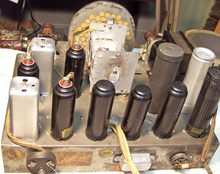
The filter capacitors (14mfd and 8mfd) were rebuilt in their original cans
using new 15mfd and 10mfd 450 volt electrolytics. My rebuilding process is
as follows. First, the insulating cardboard sleeve was removed from the
input filter capacitor - in this case there was no problem - but sometimes they
are firmly glued on and cannot be removed without first splitting the
cover. The capacitors were then chucked in my Unimat lathe and their cases
deeply scored about 1" up from the bottom. The cuts were then
completed using a hobby razor saw and cleaned up using an Exacto knife.
This leaves only a thin straight line on the case - hardly visible. The
original contents were then removed and the capacitor case cleaned inside and
out. The original positive foil was removed and the stud was cut short and
then drilled to accept a ground lug and 4-40 screw and nut. The positive
lead of a replacement capacitor was attached to the ground lug. The
negative lead of the new capacitor was extended, insulated using spaghetti
tubing, routed though a small hole drilled into the base close to the threads,
and attached to the original nut after the capacitor was mounted. The two
halves of the case were rejoined using 3/4" plumbing PVC couplings which
were wrapped with masking tape and secured using epoxy. The masking tape
was needed to slightly increase the diameter of the coupling, and also perhaps
permit the capacitor to be re-opened in the future, if needed.
Tubes
All of the original metal glass tubes were left in place. I was able to
find an NOS replacement 5Z4MG tube on the Antique
Radio Forums Classified Ads. The original 6E5 eye tube was also left
in place. It is dim, but usable (at least in a dark room!) The radio
worked very well even though the original 6Q7MG and 6A8MG tested weak. I
wished to maintain use of the original tubes if possible.
Cabinet
There's not much I could do with the cabinet, since the original finish had
been stripped (and NOT refinished). I simply left it as is. At least
it will be a simple refinish job for some future owner, since the messy part
(stripping) has
already been done, and the cabinet wood has no grain that has to be filled. New chassis washers were fitted. I used part CW5
available from Renovated
Radios. The lettering on the wooden knobs was refilled as much as
possible using gold lacquer stick. The knobs were placed on the correct
shafts! The missing chassis bolt was replaced using a standard 10-32 round
head slotted machine screw, plus a flat washer. The missing rubber
centering insert was fabricated from a rubber bushing (not as long as the
original, but it worked). One missing metal disc which fitted under the chassis washer
and allowed adjustment of the chassis height was replaced using a knockout from
an electrical box - which was almost identical to the three remaining originals!
Testing and Alignment
Once the radio chassis was reassembled and the tubes installed, power was brought up
slowly using a variac. AC power consumption was monitored using a watt meter, and a
DVM monitored the B+. When first tested, the radio powered up but there
was only some crackling noises and a few very weak stations received, even at full
volume. It was discovered that the secondary of the second IF transformer
had opened up - broken wire at the terminal. This could have been caused
by removal and replacement of the transformer's top nut for cleaning the shield.
Once this was repaired, the set worked well, even with the weak
tubes (6A8MG and 6Q7MG).
The radio was then aligned, which was more difficult than usual since the
trimmer locations are not indicated in Riders (Nostalgia Air) - but easily
determined using a DVM by selecting each band and measuring the resistance to
each trimmer. The radio performs very well, is quite sensitive and has very good tone. As
is typical of radios of this age, there is excessive speaker cone movement on
some stations if the tone control is set so as to increase the bass. I am
told that today's stations have much more bass then in the 1930's (classic
country or classis rock). The switchable selectivity IF works well -
essentially a selection of WIDE or NARROW bandwidth. WIDE (position 2)
sounds best for music. I suppose that NARROW (position 1) would be used when listening
to short wave stations which are close together.
Restoration Results
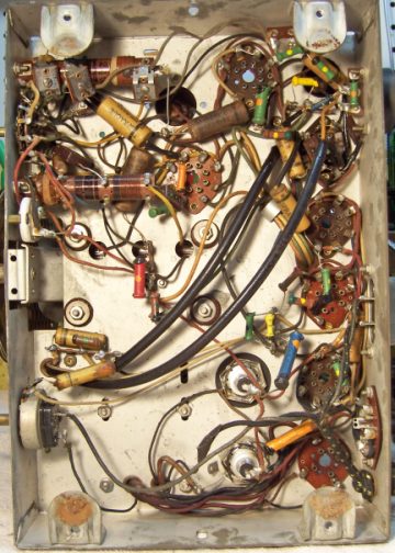
Chassis Bottom Before and After Restoration