Silvertone Model 7039 Restoration

|
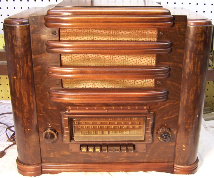
The Silvertone Model 7039 from about 1941 is
a large 9 tube superhet table radio that receives the broadcast band
and two short wave bands, as well as a shortwave "bandspread"
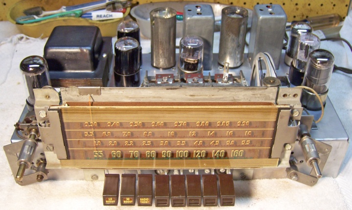
band (9.3-9.9 mHz, 31 meters). It has mechanical push-button tuning,
the "Radionet" loop antenna system, a tuned RF amplifier stage (broadcast band only), separate oscillator and mixer tubes,
push-pull
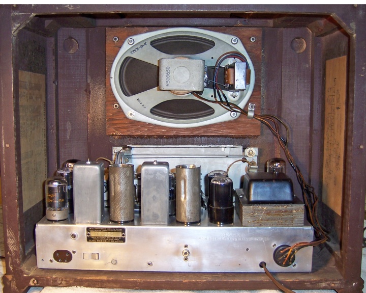
6K6 audio outputs and a large 6x9 inch dynamic speaker. The
radio had seen quite a bit of servicing in its past, including several tubes, the
filter capacitors, and several small coupling and bypass capacitors.
I decided to try
to reverse as many of these repairs as possible and to restore or maintain the original above and below chassis appearance to the extent possible. The schematic for this radio can be found on-line at Nostalgia
Air. Any part numbers mentioned in this log are referenced to
that schematic. |
My
antique radio restoration logs
Condition As Found
This radio was purchased on eBay. The seller powered it up
using a "dim bulb" tester and got no reception - just noise. There
was no shipping damage. The radio had not been restored. I
always avoid knowingly purchasing a radio that has been restored by a collector,
as many take shortcuts such as removing the original capacitors and
filters. Since it powered up and made noise, I assumed major parts
were OK (so much for assumptions!). "Radionet" is apparently
Silvertone's name for their loop antenna system - sort of like Zenith's
Wavemagnet.
Previous Repairs
-
All of the original resistors were still in place.
-
The filter capacitor had been replaced by two tacked-in
tubular electrolytics.
-
Eight small coupling and bypass capacitors had been
replaced.
-
Several tubes had been replaced.
Survey
My usual restoration procedure is to first make a complete
survey of the condition of all components. The survey results guide my
restoration strategy. If major and unique components are defective or
missing and
cannot be restored or replaced, I may elect to sell the radio rather than restore it.
I always assume that all paper and electrolytic capacitors are leaky and thus should be
replaced (I always "restuff" the original containers if possible).
Any mica capacitors are assumed OK until testing proves otherwise. Since
the radio powered up and made noises, I assumed that no major components were likely defective.
-
Half of the output transformer primary was open (which means that the radio
still would have worked, as stated in the auction).
-
The speaker field and cone were OK.
-
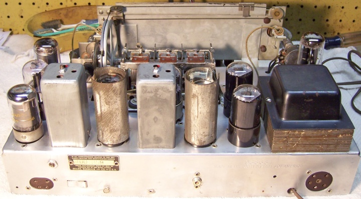
The power transformer was OK. The high voltage was balanced across the
center tap with 20 volts applied through a variac. Wattage draw was about 5 watts with full
line voltage and no load. A transformer with shorted turns will draw
much more wattage. I use a real analog watt meter and a variac for
this test.
-
All coils and IF transformers were OK.
-
The loop antenna was OK.
-
All tubes were good, except for the (non-original) 6J5 metal tube
-
The push-button tuning mechanism did not work. The pot-metal sector gear
which moved the tuning capacitor shaft was missing, and so I assume it had
broken at some time in the past. So the mechanism could not be
restored.
-
One pilot lamp was burned out (the other one failed during final testing!)
-
The dial drive rubber had deteriorated and had a flat spot - tuning was not
smooth.
-
The clear plastic dial cover had shrank and no longer covered the dial on
one side - there was about a 3/8" gap. Fortunately, the
escutcheon was still OK and had not split or shrank.
-
The "plate" antenna (for short wave, in the top of the cabinet)
had split. It was simply tin foil over cardboard.
Repairs
The Silvertone 7039 is a complex radio which is quite difficult to service. There
are many parts that are buried under other parts, and which are almost
impossible to replace without partial disassembly. In many cases, the order
of parts replacement is critical - I generally replace parts in the reverse order of
their removal. There are also several situations where there are parallel
electrical paths present which prevent accurate measurement of resistance values unless the
parallel path is broken. This requires an analysis of the schematic.
For example, resistors R9, R15, R16, and R17 form a loop such that none of them
can be accurately measured unless the loop is broken. Also, most of the
original capacitors were very leaky, which also prevented accurate measurement
of the resistors. I finally resorted to removing ALL of the capacitors
then measuring resistor values. Out of tolerance
resistors were then replaced, and capacitors restuffed and replaced. This
requires accurate notes as well as photos to prevent errors (replacing parts one
at a time is safer).
All tubes were removed. All non-original parts were removed, and
their connections documented. The tuning capacitor, dial assembly, and
dial drive mechanism was
removed for cleaning and access to other parts on top. The band
switch and on-off/tone control linkages were removed for cleaning and access. The
tuning capacitor drive assembly was removed for access and cleaning. At this
point I made BEFORE photos of the chassis bottom. I use these photos to
ensure that replacement parts and wiring are placed as close as possible to
their original positions. Some radios are subject to problems (such as
oscillation) if wiring is re-routed or lead dress is not the same as the
original. I then printed the photo and identified and marked the location
of all the resistors and capacitors (some were hidden or buried and not visible
in the photo).
The top and sides of the chassis was cleaned with GoJo hand cleaner and 00 steel
wool. Since this process may leave small steel wool fragments that can cause
problems later, I follow up with a thorough vacuuming and go over everything
with a small magnet and masking tape to pick up any stray fragments.
The tuning capacitor drive was replaced using a conical round rubber part
from my junk box. It had a center hole slightly smaller than the 1/4"
needed. So I thought it would work OK. But I noticed that as the
tuning shaft was operated, the rubber part would gradually move down the shaft
(due to its conical shape). I noticed that there was a small hole in the
tuning shaft. So I secured the rubber part to the shaft using a tapered
clock pin, which was then cut off flush.
Resistors and Capacitors
All of the original capacitors remaining in the set were restuffed using new 630 volt film
capacitors. Eight capacitors had been replaced at some point (most were in the audio
portion of the radio). I normally
attempt to reverse any previous servicing by installing original type
components. But in this case, I did not have any capacitors in my dud
capacitor stock that matched the originals. The originals had no brand name - only a
Silvertone part number and their value and voltage rating. Their
appearance was similar to the types used by GE - crimped-over ends vs. sealed
with wax. I maintain a collection of branded dud
capacitors just for this purpose (Zenith, Philco, RCA/GE, etc.) For this radio I
decided to install Sprague and other generic capacitors having the correct values, and
to restuff them using modern parts. This would look more original than the
newer white plastic components (Argonne brand) that had been installed. And I have seen other
Silvertone sets of this vintage that used Sprague capacitors (for example the 1942).
Some Sears Silvertone radio suppliers used generic capacitors (Sprague, Cornell-Dubilier
etc.),
while some others used proprietary branded parts with part numbers that match
the schematic.
In order to maintain the underside chassis
appearance, any out-of-tolerance dogbone and carbon composition resistors were replaced with the same
or similar types. I maintain a collection of NOS and used dogbone
resistors. Of course, most of these are also out of tolerance! So I
select a dogbone resistor from my stocks that has drifted to within 15-20% of the needed
value, and then repaint it to the needed value using hobby paints.
The original filter capacitor had been removed and replaced by two tacked in
tubular electrolytics. Evidence showed that the
original must have been a dual 20+15mfd 400 volt unit that was clamp mounted under the
chassis. There was a large solder-tinned area on the chassis in just the right
spot to hold a clamp mounted capacitor, and its connection points were nearby
(and had wire remnants). I found a clamp mounted dud filter in my dud
stock that would fit in the chassis where the original must have been
mounted. It was cleaned out and restuffed using two 22mfd/450 volt
electrolytics, and new wire leads were attached. The ends of the tube were
sealed using rosin/wax salvaged from RCA Radiola Superheterodyne
catacombs! A label was fabricated using MS Word, containing the original's
part number, values, and voltage rating. The clamp was soldered to the
chassis where the original was thought to have been attached. A piece of
hookup wire strung across the chassis was removed - I assumed it was placed
there by a previous service man to hold the tacked in filter capacitors in
place.
Output Transformer
The output transformer (mounted on the speaker) had an open half of the
primary winding. The speaker voice coil measured 3.7
ohms DC, so the impedance was estimated at 4 ohms. The push-pull 6K6
output tubes need a load impedance of 12,000 ohms per the tube manual.
This means that the needed step down ratio was 54.77 (square root of 12000
divided by 4). I had a Stancor A-3850 universal single or push-pull transformer
(rated at 8 watts) in my stock of output transformers. Although the needed
impedances (12000 and 4) were not included in the instruction sheet, I was able
to determine which secondary taps to use by calculating the ratios of several of
the documented impedance ratios and picking the taps that came closest to a
ratio of 54.77. Secondary taps 2 and 5 yielded a ratio of 54.4!
The mounting centers of this transformer also matched the existing transformer
mounting holes exactly.
Tubes
The metal 6J5 was replaced by a 6J5GT, as called for in the schematic.
The rest of the tubes were good and were left in place. I made no attempt
to install Silvertone branded tubes.
Cabinet
The cabinet was cleaned using GoJo hand cleaner and 00 steel wool, followed
by a treatment with Old English Scratch Cover. The incorrect knob was
replaced by the correct knob purchased from David Frush who can be contacted at parts2many@aol.com.
The clear dial cover was left as it was. It was firmly attached (cemented or
fused) to the dial escutcheon on one side. I feared that attempting to
remove it may break the cover or escutcheon. I plan on attempting to make
a replacement dial cover later. But it is not clear how it can be attached!
Testing and Alignment
Once the radio chassis was reassembled and the tubes installed, power was brought up
slowly using a variac. AC power consumption was monitored using a watt meter, and a
DVM monitored the B+. The radio came alive and worked on all
bands. The loop antenna provides the broadcast band antenna, but short
wave requires an external antenna (and ground connection). The LOW BOOST and HI
BOOST switches worked well on some stations playing music. But I noticed
that if LOW BOOST was used, excessive speaker cone excursion resulted on some
stations. I have noticed this problem on several sets. I have been
told that this is normal, and radio stations did not have so much bass when the
radio was first sold.
Next the radio was aligned. No problems were found. One IF
transformer trimmer was way off, but the rest were very close (this could be due to
a tube replacement).
Restoration Results
Chassis Bottom Before and After Restoration
NOTE: The volume knob (left side) has not yet been replaced in this
photo!