Sparton Model 10 Radio Restoration
 |
The Sparton Model 10 is an early 7-tube AC non-AVC
superheterodyne radio, broadcast band only. The set features a
double-tuned pre-selector (four section tuning capacitor) with RF
amplifier stage. It uses 2.5 volt tubes typical of the mid 1930's.
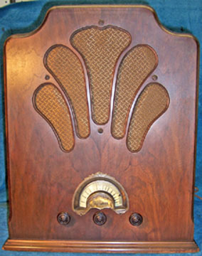
As acquired, the cabinet was in excellent condition but the grille cloth
was torn. The knobs were original. There was some loss of finish area at the bottom of the cabinet.
The veneer on the front was in excellent shape (the remainder of the
cabinet is solid wood).
The radio had seen some servicing in the past since all the tubes were
not the unusual types called for (435, 427, 480 etc.) and were all other brands. The top and bottom of the chassis appeared all
original - no parts had been replaced. This being the case, I
decided to try and retain the original top and bottom chassis appearance if
possible.
The schematic for the radio can be found on Nostalgia
Air but it is hard to read and there are several errors. |
My
antique radio restoration logs
Survey
My usual restoration procedure is to first make a complete
survey of the condition of all components. The survey results guide my
restoration strategy. If major and unique components are defective and
cannot be restored, I may elect to sell the radio rather than restore it.
I assume that all paper and electrolytic capacitors are leaky and thus should be
replaced (I always "restuff" the original containers if possible).
-
The detector plate choke (RFC) was open
-
The primary of the first IF transformer was open
-
The rest of the coils and transformers were OK, including
the power transformer
-
The speaker was OK and the field coil was good
-
All tubes were good
-
The voltage divider resistor, which was a two section wire
wound resistor, had one open section.
-
Several resistors had drifted in value up to 82% high
-
The hum balance resistor was intermittent
-
The AC power switch was not functional
-
The volume control was intermittent
Repairs
This is a very difficult radio to work on - one of the worst I have
encountered. The chassis is packed full, and components must be removed in
order to access components below them. I had the remove the combination
first detector and oscillator coil (inside the copper shield under the chassis -
see photo below), both bypass capacitor blocks and
the tone control in order to access and test components below them.
Detector Plate Choke
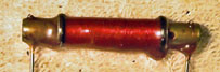 |
The detector plate choke was open. I first tried
unwinding some wire from one end, hoping to find a break. After
unwinding about 1/4 of the wire, I gave up. I cut off the existing
wire and rewound the choke using #40 magnet wire by chucking one end in my
Unimat lathe running at the slowest speed. The restored choke
was then dipped in rosin to approximate the original appearance. |
Paper-Wax Capacitors
The radio contained only three tubular paper-wax type capacitors. Most
capacitors in this radio were either mica or contained in two metal containers. The
tubular paper-wax capacitors were made by Cornell (later to become Cornell-Dubilier?)
and branded "Cub". They were quite unique in construction and
could not be re-stuffed in the conventional manner. Here
is the procedure I used to restore them. The results are shown below.
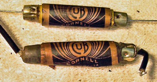 |
The capacitor on the bottom is an original Cub
capacitor. The capacitor on top is a reproduction using a new film
capacitor, while retaining the original label and end caps. |
Bypass Capacitor Blocks
There were two bypass capacitor blocks in this radio. One contained
three 0.5 mfd capacitors (one high voltage and two low voltage). The other
contained seven capacitors or either 0.2 or 0.3 mfd. Two were high voltage
and the remainder low voltage cathode bypass capacitors. The cans were
opened by removing a cardboard cover and the contents removed
mechanically. The capacitor block containing three 0.5 mfd capacitors was
rebuilt using three 0.47 mfd 400 volt radial film capacitors. The original
wire leads were re-used in this case. The other capacitor was rebuilt
using six 0.47 mfd 400 volt radial film capacitors and one 0.47 mfd/630 volt
film capacitor (this one is across full B+). New wire leads were used in
this case. This capacitor was filled with rosin to stabilize the contents
and the cardboard covers reinstalled.
Mershon Filter Capacitor
The Mershon filter capacitor was two sections: 8 and 16 mfd (voltage
unknown). The main part of the capacitor was below the chassis, secured by
a clamp. The terminals on top were covered by a clamped-on shield.
The capacitor was removed from the set. I wanted to retain the original
terminals and appearance as much as possible. I marked the area on the
nickel plated copper can where the mounting clamp was located, then cut the can
in two pieces using a hobby razor saw. The contents were then removed and
the parts cleaned. Lugs were attached under the original aluminum terminal
bolts and new 450 volt electrolytics were mounted. I used 10 mfd for the 8
mfd section and 22 mfd for the 16 mfd section. The grounds were soldered
to the inside of the top part of the can. The two halves were then
rejoined using the original clamp and secured in a couple of places using
solder. The clamp covers the sawed joint and the solder is barely visible.
IF Transformer
The copper shield was removed from the top, revealing the coil and
trimmers. The top coil (primary) was open. Luckily the break was
right where one end of the coil attached to the terminal (usual failure
point). I was able to scrape the remaining wire clean and form a splice
from one piece of wire from a piece of stranded wire. The splice was
wrapped around the terminal and soldered. The other end was then laid over
the stub, the stub folder over, and the wires soldered. This established
continuity.
Resistors
There were five resistors that needed to be replaced. They were the old
style "dog bone" types. But these were unlike any that I had
seen before: instead of a color dot for a multiplier, these used a color
band. I found some dog bone resistors in my junk box
and NOS dog bone stock that had drifted to close to the resistances needed. I repainted them using enamel purchased from a hobby store. I assume that the resistors took 60+ years to drift by
40-60%, so future drift would not be excessive
(at least in my lifetime). To me, maintaining the original look is
more important than long term reliability of the radio.
There was a wire wound voltage divider resistor that had one section open
(the 5500 ohm lower section). From the voltage table, I calculated that
this section dissipated about 2.5 watts. The replacement would have to be
about 12000 ohms 10 watts adjustable. I could not find anything like that
available today (10K and 25K was available). So I decided to simply shunt
the open section with a 6K 5 watt wire wound resistor that just happened to
measure 5.6K. The repair is hardly visible, although I would have
preferred to replace the entire resistor. My fear is that the open section
could become intermittent at some point.
The adjustable hum control pot showed intermittent operation. Cleaning
the slider and resistance element did not help. I determined that the problem
was the riveted connection between the slider and frame/contact. The pot
was repaired by soldering a piece of fine wire between the slider and
terminal. I formed a small coil in the wire for slack needed for
adjustment and to avoid strain on the wire. This restored normal operation
of the control.
Other Repairs
- The AC power switch (a toggle switch attached to a bracket on the back of
the volume control) was not functional. There was no way to open up
the switch, and no available opening to inject contact cleaner. I
drilled a small 1/16" hole in the switch housing (limiting depth) and
was able to inject Big Bath cleaner. By rapidly operating the switch
the switch was OK (contact resistance less than 0.2 ohms).
- The volume control was disassembled and the wiper and wirewound element
cleaned.
Chassis
The chassis and top components were cleaned using GoJo, steel wool, and
toothbrushes.
Testing
After completion of restoration, the radio was connected through a watt meter
to a variac and the power gradually applied while monitoring the B+. A 50'
indoor antenna was connected. The radio immediately came alive and worked
well. The radio was then aligned. As found, the set was way out of
alignment. In order to adjust the IF transformers, the shields had to be
removed - there is no way to adjust the trimmers with the shields in
place. The radio works very well with very good tone and sensitivity for an
early superhet.
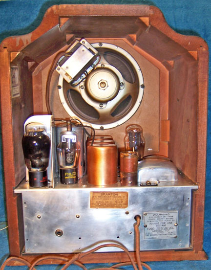
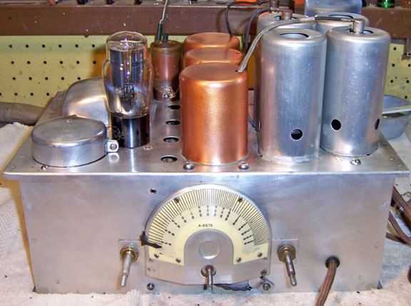
Restored Chassis. The large copper cylinder is the combined mixer and
oscillator coil shield. The two metal boxes on the right are bypass
capacitor blocks. The cylinder on the left is the Mershon filter
capacitor.

Below: Front view of restored chassis. The dial mechanism is quite
unique in that the pilot lamp rotates behind the dial as the radio is
tuned. The dial pointer also rotates in front of the dial.
Below: Back view of restored radio.