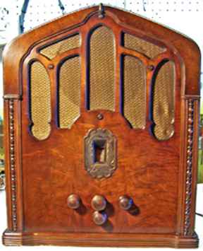
Zenith 216-2 Zenette Restoration
 |
The USA stock market crash of 1929 and the following Great Depression
resulted in a market mismatch with Zenith's early 1930's line of expensive radios.
So Zenith developed a low cost product line in order
to better match market needs. In order to distinguish those radios from their
high-end line, they branded them "Zenette" rather than
Zenith. Although supposedly a low-end radio, the build quality of my
radio is very high.
The Zenith Model 216-2 Zenette is the more rare 25-30Hz model.
These radios were only used in the Niagara Falls area of New York and
Canada, where 25hz AC power was being produced.
The
circuit is a conventional 7-tube superheterodyne that receives only the
broadcast band. It features a tuned RF amplifier and separate
oscillator and mixer stages. It uses 2.5 volt tubes, typical of the early
1930's.
The radio had seen some servicing in the past but had not been hacked excessively.
This being the case, I
decided to try and retain the original top and bottom chassis appearance if
possible.
The schematic and parts list for the radio can be found on Radio
Museum (Nostalgia Air/Riders has only the schematic). |
My
antique radio restoration logs
Survey
My usual restoration procedure is to first make a complete
survey of the condition of all components. The survey results guide my
restoration strategy. If major and unique components are defective and
cannot be restored or replaced, I may elect to sell the radio rather than restore it.
I assume that all paper and electrolytic capacitors are leaky and thus should be
replaced (I always "restuff" the original components if possible).
And most original resistors would have drifted and be out of tolerance range.
-
A type 5Z3 tube had been installed to replace an 80 (yikes -
hopefully no power transformer damage!)
-
A type 2A6 tube had been installed to replace a type 55 (not
a good match).
-
The type 59 output tube was VERY weak.
-
The original filter capacitor block had been replaced by two
Aerovox 8mfd box-type capacitors inside the original metal cover. One of these
capacitors had been replaced by a tubular filter under the chassis
(obviously a second repair).
-
All of the original paper-wax capacitors and dogbone type
resistors were still in place.
-
The power transformer was OK. It was a 25-30Hz
transformer, but had an optional capacitor across the speaker field coil
marked as "60 cycles only" in the schematic, so I assumed it
would work on 60Hz. I tested it on 60hz with a watt meter and a variac.
It drew almost no power (5 watts or so) unloaded at 120 volts input. All
output voltages were correct,
and the high-voltage winding was balanced on each side of the center tap.
-
The speaker field and output transformer were OK.
-
All RF coils and transformers were OK.
-
The original power cord was usable - it had only one bad spot about
1' from the plug.
-
The power switch on the volume control was defective but likely needed only
cleaning (the dreaded BradleyStat type control). The volume control
itself also needed cleaning.
-
The tone control potentiometer was intermittent and needed
cleaning (another BradleyStat).
-
Almost all original dogbone type resistors were out of tolerance
by 30-100%.
-
One speaker socket terminal was broken loose from its
mounting (this was left in place, since there was no obvious way to repair
it, and it worked OK once the speaker lead connector was attached).
-
The two Candohm type (metal cased) power resistors were both
OK, fortunately.
Cleaning
I normally clean the chassis before starting restoration.
I first blew off the above and below chassis dust with an air compressor.
The chassis was then partially disassembled for access and cleaning. The
tuning capacitor and dial drive mechanism was removed as a unit after
unsoldering the leads and ground braids. I had to remove the mixer coil shield cover in order to gain access to
the screws and spacers that held tuning capacitor shield to
chassis. The filter capacitor block cover was removed. The volume and tone controls and
their bracket were then removed after disconnecting all wiring from the
controls. It was very difficult to manipulate
the controls and bracket out of the chassis - there was no room to remove the
controls before removing the bracket, and the bracket could not be removed
without first removing the controls! So I had to loosen the control nuts,
leave the controls in place, and bend the bracket slightly in order to remove
it.
The chassis and top components were cleaned using GoJo, steel wool, and
toothbrushes. The tuning capacitor was removed from its shield cover and cleaned with soap,
water, and toothbrushes and then dried using a heat gun and lubricated.
The complex brass helical ring-and-pinion gear dial drive mechanism was removed, disassembled,
cleaned, and lubricated.
Repairs
All paper capacitors (13) were rebuilt in their original cases
using modern 630 volt film capacitors in order to maintain the original
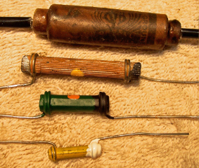
under-chassis appearance. The radio used Dubilier Cub type capacitors,
which are difficult to restuff. My process for restuffing Cub capacitors
is documented here.
All the Cub capacitors were originally marked with paint: either ORANGE (for .1mfd),
YELLOW (for .05mfd), or GREEN (for .25mfd). Cleaning the cardboard case
removed most of the paint, so it was replaced after rebuilding. I suppose
this was to simplify assembly, since the person assembling the radio would not
have to read the label on the part!
Main Filter Capacitor Block Replacement
I fabricated a replacement main filter block using two 10mfd/450 volt tubular
electrolytic capacitors. The original block was two 8mfd/500 volt
capacitors. There was evidence remaining that the original capacitor block
had terminal lugs (there were remains on some of the wiring).
- Cut a piece of insulation material (Fish Paper) to the pattern of the base of the outer metal
capacitor cover (so it would be largely hidden when the cover is in place).
- Cut a piece of hard rubber (1/8" thick) to fit inside the outer metal cover
(you could also use 1/8" or 1/4" plywood)
- Sandwiched these two items together and drilled 4 holes at the corners for
6-32 hardware, spaced so that the ground lugs would not contact the chassis
or metal cover..
- Installed 4 ground lugs above and below, screwed together with 6-32 screws and nuts
- Installed 2 10uf 450 volt tubular caps on the top side, connected to the ground
lugs
- Reattached the cover to the chassis. The retaining screws passed
through the Fish Paper thus holding the components in place.
- Reconnected the original wiring to the bottom ground lugs
Dogbone Resistor Replacement
All original resistors more than 20% out of tolerance were replaced (there
were 10). I
used dogbone type resistors as were used originally. I picked out NOS and
used dogbone resistors from my stock and junk box that had drifted to the correct needed resistance and
then repainted them to match the original resistor's color codes. The
replacements may continue to drift, as would most new carbon composition type
resistors. But to me, maintaining the original look is more important than
long term reliability of the radio.
Volume and Tone Control Repairs
The volume and tone controls were of the BradleyStat type, which are
difficult to repair or clean. My process for restoring them is as follows:
- Grind down off the head of the brass rivet on the back that holds the center rear terminal and also
the back cover. Be careful not to damage the terminal, since it must be
reinstalled, and take off only the HEAD of the rivet and none of the shaft
(just enough to free the terminal lug).
- Remove the center terminal lug and the back cover of the control
- Remove the wiper - it can be pulled from its pivot (careful not to bend
it).
- Clean the wiper and resistance element with lacquer thinner on a Q-tip. Note
that the wiper does not directly contact the resistance element, which is wound with
circles of wire. Use a minimum amount of lacquer thinner so as
not to damage the resistance element.
- Clean the switch contacts on the volume control (using lacquer thinner on
a Q-tip, Caig DeOxit, and finally 600 grit paper when all the above failed
to revive the contacts). Any sanding residue is then cleaned off
using lacquer thinner.
- Reinstall the wiper and test the control and power switch for
functionality
- Install the back cover
- Replace the center rear terminal lug on the rivet shaft, and then solder the terminal lug to the rivet to hold the back cover and terminal lug in place.
Other Repairs
- New type 59 and 55 tubes were installed
- A type 280 rectifier was installed to replace the 5Z3 (the socket is
marked 280 rather than 80)
- About 1' of the line cord was cut off and the plug reinstalled. The
line cord was then safe to use.
- One grid lead was frayed. It was replaced (in order to do so I had
to remove the transformer shield)
Testing
After the radio was completely reassembled, power was applied through a
wattmeter and fused Variac. Power was brought up slowly while monitoring
the B+ voltage. Normal B+ was reached with only 100 volts applied, and the
radio worked. I assume that the high B+ was due to my using a 10mfd input
filter capacitor instead of the 8mfd originally used. Operating the radio
on 60Hz power (vs. 25Hz) may have also contributed. I tried replacing the
10mfd input filter capacitor with a 4mfd unit. The result was that the B+
was then correct (270 volts) with 110 volts input (rated input AC is 115
volts). The hum level was slightly higher but not objectionable. So I
will operate the radio through my bucking transformer (set for 110 volts out) any
time it is used (which I normally do for all early AC sets).
The radio was then aligned. It performs very well - it has excellent
sensitivity (due to the tuned RF stage) and good tone also. It performs as
good or better than other early 1930's radios (RCA, GE, Philco) - IMHO.
|
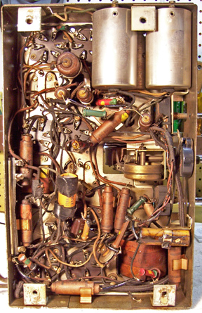
Chassis before restoration |
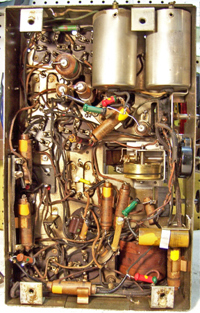
Chassis after restoration (for some reason, the orange
paint on the capacitors shows as yellow) |
 |
 |
|
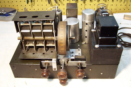
Restored Chassis (the box on top of the power
transformer covers a fuse which selects 110 or 220 volt operation) |
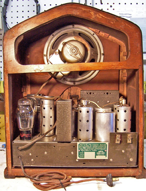
Cabinet Rear |
 |
 |

