Zenith 5D625 (5-D-625) Restoration

|
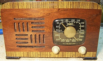
The Zenith 5D625 from 1942 is a 5-tube AC/DC Superhet with Wavemagnet
loop antenna. It only receives the Broadcast band. The cabinet
is walnut veneer with photo-finish (picture of wood) trim. Other models share the same
chassis 5B01 including the 5D610 and 5D610W bakelite sets. The schematic for the
5D625 can be found on-line at Nostalgia
Air. Any references to part numbers refer to that schematic.
The radio had seen typical repair shop type servicing in the past. I decided to try to
reverse all previous servicing to the extent possible, yet get it working. |
My
antique radio restoration logs
Condition As Found
This radio was purchased on eBay. The cabinet and knobs were
in excellent condition. The power cord had been cut off and the radio sold as not
tested. The often missing original back
cover was present but very fragile.
Previous Repairs
-
All the tubes were replacements. Two were metal types,
not used by Zenith.
-
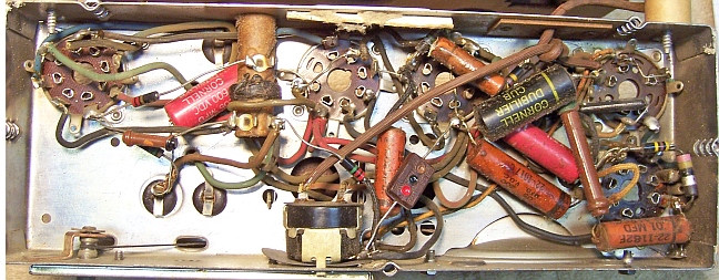
Three wax/paper capacitors had been replaced: C2, C3 (line
bypass capacitor) and C7. All replacement capacitors were CD branded,
but were different types and ages. The original filter
capacitor was still in place.
-
All of the original wiring and resistors were still in place.
-
The volume control and switch had been replaced.
Survey
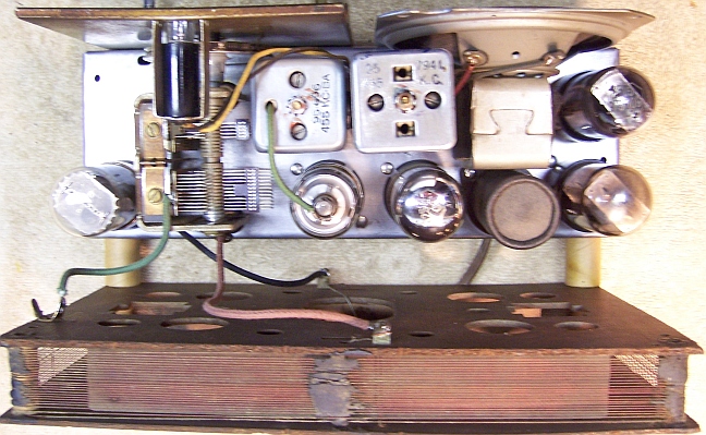
At first observation, the radio was a typical 5 tube AC/DC
superhet using octal tubes. Like in the previous year Zenith models (e.g.
6D525), it used a 12K7GT (with a grid cap) rather than a 12SK7GT in the IF
amplifier stage. When I pulled the chassis, I could not find an output
transformer! It was not mounted on the speaker nor under the chassis. The
speaker was original (per the parts list) and was a field coil type. But there
were only two leads to the speaker. One lead was from the 50L6 output tube
plate, and the other from B+. The leads to the speaker went to the field
coil! So somehow, the speaker field coil not only magnetized the core, but
also acted as the output transformer. On the schematic diagram, there is an
arrow pointing to the usual position and connections of the output transformer,
but labeled "speaker field". The field coil in this case is NOT used
to assist with B+ filtering - the radio used resistors for this purpose. I have
never seen this before used in any radio. When I asked about this circuit
on Antique Radio Forums,
someone recalled seeing at least one other example of this circuit.
My usual restoration procedure is to first make a complete
survey of the condition of all components. The survey results guide my
restoration strategy. I usually never apply power to a radio before
restoration, even through a "dim bulb tester" or variac "to see
if it works". But there was signs of damage where the speaker leads
enter the combined field coil/output transformer, and there were bare areas or
the wiring exposed. Perhaps someone was trying to measure the field
coil resistance? I had to know if this speaker was working. So I applied
power through a watt meter and variac and monitored the B+ using my DVM. I
slowly applied AC power in increments of about 10 volts, allowing plenty of time
for the capacitors to reform before increasing the voltage. At about 70 volts
input, the radio started making noises and some stations were received. But the
B+ started dropping - a symptom of leaky capacitors. So I stopped the
test, satisfied that the speaker was working. I did learn that the volume
control and tuning capacitor were "scratchy" - useful information.
If major and unique components are defective or
missing and
cannot be restored or replaced, I may elect to sell the radio for parts rather than
to restore it.
I always assume that all paper and electrolytic capacitors are leaky and thus should be
replaced (I always "restuff" the original containers if possible).
Any mica capacitors are assumed OK until testing proves otherwise.
-
The AC power switch was was initially bad, but responded to a quick spray of
GC Big Bath.
-
The original rubber AC power cord was cut off. The remnants were very stiff
and badly deteriorated.
-
The speaker cone and field coil were OK..
-
All RF coils and the IF transformers were OK.
-
The pilot lamp was burned out.
-
The 50L6GT tube was good. The 35Z5GT was bad (open filament). This tube acts
as a fuse if there is a B+ short or bad filter capacitor. This usually also
takes out the pilot lamp. The remaining tubes were weak (also inappropriate
metal types). The burned-out 35Z5 is likely what killed the radio.
-
All resistors were in tolerance, including the wire wound types.
-
Most of the wiring was rubber covered. If moved even the slightest amount,
the insulation would fall off. All of this wiring would have to be
replaced, including the leads to the two IF transformers. The cloth covered
wiring to the pilot lamp socket was shorted inside the socket, and one of
the leads to the speaker field coil (cloth covered) was frayed and in danger
of shorting to the chassis.
-
The tuning capacitor drive pulley was loose on the tuning capacitor shaft,
resulting in backlash when tuning.
Repairs
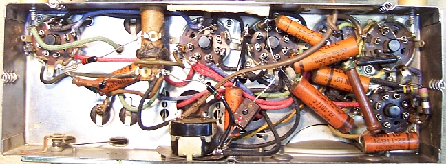
Before starting repairs I made BEFORE photos of the chassis top and bottom. I use these photos to ensure that replacement parts and
wiring are placed as close as possible to their original positions. Some
radios are subject to problems (such as hum pickup or oscillation) if wiring is re-routed or
lead dress is not the same as the original.
In Zenith schematics, all resistors and capacitors having the same
value have the same part number call out. So for example, there may be
multiple R2's or C4's on the schematic. Before I start work on the chassis
I annotate the schematic and under chassis photo so that all parts have unique
identifiers. I usually add an alphabetic suffix, so that the part numbers
are thus R1A, R1B, etc. I then annotate the chassis photo with these unique part
numbers with a red felt-tip pen.
All tubes were removed. The chassis was very clean, with no rust - just
very dusty. It was first cleaned off with a vacuum cleaner. The chassis
was then cleaned with a tooth brush and vacuum cleaner to remove any remaining
dust. The tuning capacitor was not removed for cleaning, since it is
mounted using bent-over tabs through rubber grommets. The tuning capacitor was
cleaned by spraying it with GC Big Bath spray cleaner.
Wiring
The AC line cord was replaced with a replacement vinyl cord with molded plug.
All of the rubber covered wiring was replaced using cloth covered stranded and
solid wire available from Radio Daze and
other sources. I use their "unrated" wire rather than their 600 volt
rated wire (which is much too large for antique radio repair work). It is
available in 8 colors. One of the colors used in Zenith radios (a grayish
green) is not available. I normally use green or black to replace this
wire. Their solid and stranded wire is 20 gauge, which is really too large for
Zenith repairs (original Zenith solid wire is about 24 gauge). But that is
all I have been able to find in cloth covered wire.
One of the leads to the speaker field/output transformer was replaced using a
similar type wire from my junk box. It was spliced to the lead on the speaker
after cutting and stripping it close to the field coil. Afterward, both speaker
leads were reinforced using several layers of GC Service Cement, followed by a
layer of cloth tape, and do not like to use modern plastic covered wire.
Tuning capacitor pulley repairs
The hub of the tuning capacitor pulley was pot metal. Originally it was
inserted through a hole in the pulley and then peened over to retain it.
But wear had allowed some rotational motion. A previous owner and
attempted to solder the hub to the pulley. But that did not work, since one
cannot solder to pot metal! I did not want to risk damaging the pot metal
hub by banging on it with a hammer! So I cleaned off all the solder I could. I
then drilled a small hole through both the pulley and the edge of the hub using
a numbered drill and Dremel Moto Tool. I then inserted a tapered clock pin into
the hole and clipped it short. I then applied epoxy to the area around the pin
as well as on the back side of the pulley in order to secure the pin in
place. That seemed to work. I'm not sure how long this repair will
continue to work, but it did eliminate backlash when tuning.
Filter Capacitor
The original power supply filter capacitor C9-C10-C11 was removed and restuffed.
It was a 30+20+20mfd @ 150 volt twist lock type capacitor. It was restuffed using two
22mfd 160 volt radial capacitors and a 22mfd/160 and 10mfd/160 volt capacitor in
parallel (I did not have a 33mfd/160 volt in stock, and the 33mfd/350 volt I did
have was
too large to fit in the can). My
procedure for restuffing FP type can capacitors is as follows (there are many
discussions and examples with photos on Antique
Radio Forums):
- Remove the cardboard cover. In this case I had to use a heat gun to soften the tar
holding it to the can.
- Uncrimp the bottom using diagonal cutters (try to
minimize damage to the outside of the can)
- Remove the mounting ring, the outer terminal board, the almost liquid
gasket material behind, and a second fiber board, cutting the aluminum leads to the capacitor body to free up the terminal
boards.
- Remove the can contents using a heat gun to release the tar, followed by a
thorough cleaning using mineral spirits. In this case, the foil roll
could be removed without heating, and the remaining tar removed by
mechanical means.
- Remove the sealer/gasket material between the two terminal board layers
using a small screwdriver and an Exacto knife. Clean off any remaining
material using lacquer thinner. Both sides of the two terminal boards
must be very clean, since they will be glued together using epoxy. The
two terminals are secured between the two boards.
- After the epoxy hardens, connect the three replacement capacitor positive leads to the original terminals by
drilling small holes through the terminal boards close to the terminals,
passing the leads through, and soldering them to the terminals on the
outside.
- The common ground lead is passed through a small hole drilled near
one of the capacitor ground/mounting tabs. The hole is located by
temporarily replacing the mounting ring (there is a tab that fits into a
notch on the outer terminal board) and marking the location near one of the
three mounting twist tabs. This lead is not soldered
to the ground lug until after the capacitor is secured in the chassis
mounting wafer (otherwise the solder would prevent the lug easily passing
through the hole in the mounting wafer or could damage the wafer - ASK ME
HOW I KNOW THAT).
- Reinstall the terminal boards with attached replacement capacitors and the
mounting ring and restore the crimp
around the base. I start the crimp using a screwdriver and then
flatten it out using a plastic tipped hammer.
- Reinstall the cardboard cover (it was not glued - just held by friction).
The cover hides any signs of the bottom crimp being disturbed. Be
aware that the capacitor body is electrically HOT (connected to one side of
the AC line), so the cover is an important safety
feature. The chassis itself is isolated from the AC line by a
capacitor.
Wax/Paper Capacitors
Three original Zenith wax/paper capacitors had been replaced in previous servicing:
C2 (22-829, .05mfd/200v), C3 (22-1017, .05mfd/200v) and C7 (22-243,
.01mfd/400v). I maintain a stock of branded (Zenith, Philco etc.) as well as generic
(Sprague, CD etc.) dud capacitors just for this situation. I was able to find
original Zenith duds for C2 and C7. But I did not have a Zenith 22-1017 in
stock, and was forced to use a Zenith 22-212C instead (.05mfd/400v).All of the original Zenith paper capacitors as well as the Zenith duds
were rebuilt in their original cases
using modern 630 volt film capacitors in order to maintain the original
under-chassis appearance. My re-stuffing process is documented here.
Cabinet
The cabinet was cleaned using GoJo (White) hand cleaner, applied and then
wiped clean using Toolbox White Rags (soft, smooth paper towels made from rags). The
knobs were cleaned using my old Heathkit ultrasonic cleaner and dilute ammonia,
followed by rinsing and drying.
Testing and Alignment
Once the radio chassis was reassembled and the tubes installed, power was brought up
slowly using a variac. A DVM monitored the B+. The radio came to life immediately and worked.
The tuning capacitor was scratchy when adjusted. I first thought it had plates
that were rubbing. To check this, I temporarily disconnected any leads from both
stators. I then connected a 9 volt battery and pair of antique radio
high-impedance head phones in series between each stator terminal and the
capacitor frame. As the capacitor was rotated, no sounds were heard. This
meant that the plates were not touching. The other possibility was that there
was dirt and/or grease between the rotor shaft and the brass grounding fingers.
The fingers were riveted to the capacitor frame, and thus could not be removed
for cleaning. So instead I used pipe cleaners and lacquer thinner to clean the
contact areas as the shaft was rotated. After this treatment, the scratchiness
when rotating the capacitor was gone. My normal procedure is to remove the
capacitor from the radio and clean it using an ultrasonic cleaner using dilute
ammonia solution. But in this case, I did not wish to remove the capacitor since
it is not mounted using threaded studs, but rather bent-over tabs through rubber
grommets.
For alignment I isolated the chassis using an isolation transformer (since my
signal generator is grounded and this is a hot chassis radio). But alignment of
the IF transformers was difficult. There was considerable hum and distortion,
and also the set could break into oscillation as the IF transformers were
peaked. So I got the IF transformers close to their correct frequencies and then
disconnected the generator and peaked the transformers using a broadcast
station. The antenna and oscillator trimmers were peaked using this same method
- a known broadcast station at 1400 kHz on the dial.
Restoration Results
Most restoration objectives were met. I was able to restore the radio to its
original condition prior to servicing except for one wax/paper capacitor. That
capacitor Zenith 22-1017 was replaced with another Zenith part with the same
value (different voltage rating). The non-original volume control and switch
were left in place, since they were good, and good original parts are likely not
available.
Chassis Bottom Before and After Restoration


Restoration Completed Photos


