Zenith 5-R-337 (5R337) Chairside Restoration
 |
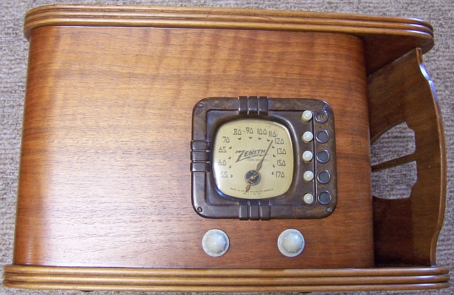
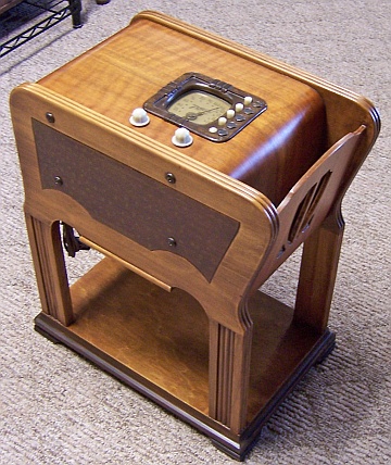
The Zenith 5-R-337 (5R337) from 1939 is a 5-tube AC superhet circuit
radio in a very small chairside cabinet with attached magazine rack. It receives the standard broadcast band
only, and has push-button automatic tuning. This chassis does not
use a Wavemagnet (loop) antenna, and requires an external antenna wire.
The set had seen extensive servicing and a VERY sloppy electrical restoration in the past.
I decided to try
to reverse any previous repairs and restore the original top and bottom chassis appearance
to the extent possible.
The schematic for the Zenith 5-R-337 can be found on Nostalgia
Air. Any part numbers will refer to numbers on that schematic. |
My
antique radio restoration logs
Overview
This radio was purchased at the 2012 Antique Wireless
Association conference and flea market in Charlotte, NC. The cabinet
finish appeared at the time to be original and was in excellent condition. One
plastic knob skirt was broken. When I searched for a replacement in the
flea market, it was discovered that the broken knob was a reproduction. So
it was replaced by a similar reproduction (they are whiter than original knobs). I
noticed that the power cord had been replaced, as was the grille cloth and
cardboard backer. The usual asbestos sheet (heat shield) had been replaced
by a piece of aluminum foil. But there were no other outward signs of
restoration, such as new wiring or replaced parts. I always attempt to
avoid purchasing radios that have been restored by collectors, and am looking
for either all original examples or those which have been "lightly
serviced" in the distant past. No statement was made by the seller as
to the radio's working or restored status. The 6X5 rectifier tube was originally
missing. That was slightly worrying, since the 6X5 tube sometimes fails
catastrophically taking out the power transformer.
After some research, the cabinet appears to have been
refinished, although very well done (at this writing, I am still not 100%
sure!). It is not shiny, and there are no sags, drips or runs in the
finish. The restorer even made an attempt at reproducing the faux finish
on the sides. It fooled me, but I have never seen an original example.
This radio is quite difficult to work on since the speaker is
not mounted on the chassis, but rather is mounted in the chairside cabinet. The
speaker lead wires are permanently attached, and no plug is used. So one of the first
things I had to do is to disconnect the speaker wiring under the chassis, so as
to avoid damaging the wiring, speaker cone or output transformer through handling.
Alternatively, the speaker can be bolted to the chassis in the usual manner
while the radio is serviced.
Previous Repairs
Once the chassis was removed from the cabinet and I had my first
look at the underside, my heart sank! This was one of the worst examples of a recap (capacitor
replacement) I have seen! All
the seven replacement bypass and coupling capacitors were Sprague orange drops mostly just
hooked to and soldered to the clipped leads of the original components - very
messy! All of the original resistors looked to be in place, and none had been
replaced. So whoever did this "restoration" did not bother with
replacing out-of-tolerance resistors (and most WERE WAY out of tolerance!) When
the remnants of the original components were later removed, it was discovered
that in several cases, the same component had been replaced twice before
(two component wire stubs were found on a single lug)! Two definite examples of
this were the two audio coupling
capacitors C9. The filter capacitors had also been replaced by modern
tubular units. The originals were 8mfd. The replacements were 10mfd
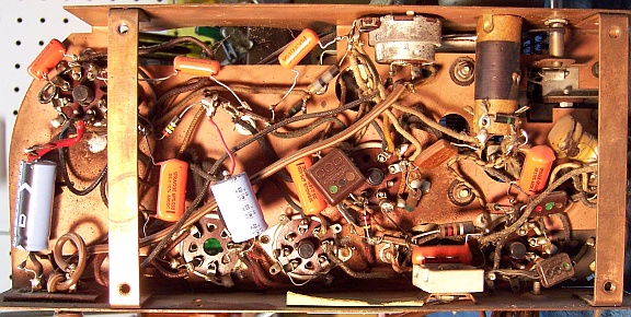
and 22mfd 450 volt units. Here is the chassis bottom as received:

I did a quick test of the power transformer by applying about 20 volts from a
fused variac and measuring the high voltage winding. It showed balance
across the center tap, indicating no shorted turns or other serious
problems. So the 6X5 tube was replaced, and the radio powered up slowly on a variac while
monitoring power usage with a wattmeter and B+ voltage with a DVM. The radio actually worked. But I could not live with this mess! I
had most of the original Zenith dud paper capacitors in stock needed to reverse the "restoration".
I collect Zenith and other branded wax capacitors just for this situation.
These are of course restuffed with modern components before use. However I had no clue
as to what the original filter caps looked like - they appeared to be individual
axial lead tubular electrolytics just looking at the parts list and where the
replacements were mounted. And of course, I had no clue how the original wax capacitors were placed and connected. I would have to find an
un-restored (or largely original) photo of a chassis 5528! And I have had almost NO luck finding original
Zenith dud filter capacitors, even from the good folks on the Antique Radio
Forums Classified ads (most collectors apparently just toss them away!)
I did get a few original under-chassis photos of similar radios
from the good people at Radio Museum,
by asking for help on their Forum. These were VERY helpful for restoring
most original component placement, but these photos did not provide photos of the
original filter capacitors (they had apparently been replaced). It
appeared that all of the original wiring in my radio was still in place.
-
The power cord
been replaced by a new brown vinyl cord with old style acorn plug (the
original would have been a molded plug). The cord used was the thicker
type - much larger than the original.
-
The grille cloth and cardboard backer board had been
replaced.
-
The asbestos heat insulation had been replaced by a piece of
aluminum foil.
-
It appeared that all knobs and push buttons were modern
reproductions.
Survey
My usual restoration procedure is to first make a complete
survey of the condition of all components. The survey results guide my
restoration strategy. If major and unique components are defective or
missing and
cannot be restored or replaced, I may elect to sell the radio rather than restore it.
I always assume that all paper and electrolytic capacitors are leaky and thus should be
replaced (I always "restuff" the original containers if possible).
Any mica capacitors are assumed OK until testing proves otherwise. Since
the radio actually worked, there were obviously no serious component problems.
Only the resistors and tubes were tested.
-
Seven resistors were out of tolerance - only one was close
enough to its original value to use.
-
There was some frayed wiring to the speaker, where the leads
enter the field coil.
-
The 6X5G tube was missing and was replaced by a Zenith
branded tube. The 6Q7G had been replaced
by a 6Q7GT. The remainder of the tubes were the correct G types, and
the one tube shield was present. Testing showed that the 6A8G (branded Zenith
but likely not original) was weak, and the 6K7G (not original) was very
slightly weak but likely usable. The 6K6G (not original) was OK.
The 6A8G was replaced, and the 6Q7GT replaced by a 6Q7G.
Repairs
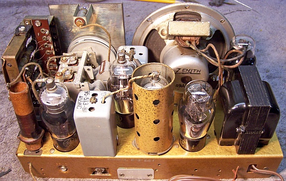
All tubes and shields were removed. Before starting repairs, I took photos of the chassis
top and bottom so that routing of wiring and component placement could be restored.
Lead dress is often critical in radios.
In Zenith schematics, all
resistors and capacitors having the same value have the same part number call
out. So for example, there may be multiple R2's or C4's on the schematic.
Before I start work on the chassis I annotate the schematic so that all parts
have unique identifiers. I usually add an alphabetic suffix, so that the
part numbers are thus R1A, R1B, etc. I then annotate the chassis photo with
these unique part numbers with a red felt-tip pen. I then removed all
of the non-original capacitors, documenting their locations
and connections. When I replace a component, I
always remove the original part completely from a terminal. Other
components such as mica capacitors connected at the terminal are protected from heat using old medical
clamps (hemostats). Excess solder is then removed using a solder sucker in order to
expose terminal holes for reattachment of the rebuilt or replaced component.
The tuning capacitor and automatic tuning assembly were then removed. The
tuning capacitor grommets needed replacement. The cardboard cover around
the automatic tuning unit was in several pieces as found. The tuning unit
had to be removed to repair it. This is a very difficult and dangerous
task! 7-8 wires have to be disconnected in order to remove the tuning
unit, many of which go to the manual/auto switch which is part of the tuning
unit. Obviously each lead needs to be identified so that it can be
restored to the proper lug on the switch. In a couple of cases, the wire
colors are not obvious. In these cases, the termination point of these
wires was traced and noted.
The top of the chassis was cleaned with GoJo hand cleaner and 00 steel
wool. Since this process may leave metal residue, I then went over the
chassis with a vacuum cleaner followed up by a small magnet. The tuning capacitor was cleaned in an old Heathkit ultrasonic
cleaner with dilute ammonia. After drying, the ball bearings were lubed with
distributor cam lubricant. The three tuning capacitor mounting grommets
were replaced using 5/16"
vinyl grommets.
Resistors and Capacitors
None of the original Zenith capacitors remained. All the replacement capacitors were removed, noting where they were connected. Their original
component wiring stubs were then removed from the terminals to confirm the connection
points. The Radio Museum photos provided some hints as to component
placement. Using the Zenith parts list, I found correct original Zenith
wax capacitors to reinstall. In a couple of cases I did not have the exact
Zenith part number in stock, so I used a replacement with the same value. These capacitors were rebuilt in their original cases
using modern 630 volt film capacitors in order to restore the original
under-chassis appearance. I reseal the cardboard tubes using rosin
salvaged from servicing RCA Radiola Superheterodyne catacombs (it melts at a low temperature and will not damage
the replacement capacitors). Here
is how I restuff Zenith tubular capacitors.
Most resistors in the set were carbon composition types, and most were 1/2
watt 20% units. A few were low-value wire wound types. Seven carbon
resistors were not in tolerance and
were replaced using the same type resistor, although I was forced to use 10%
tolerance resistors in most cases. All the wire wound resistors were in
reasonable tolerance.
Replacement filter capacitors were fabricated. I picked out two tubular
electrolytics from my dud stock that were the correct length and had axial wire leads. These
were cleaned out leaving the empty tube. The tubes were then restuffed
using 10mfd 450 volt axial electrolytic capacitors (the originals were both 8
mfd at 350 and 450 volts). These were wrapped in
strips cut from paper towels in order to center them and to prevent the contents
from falling out. The ends were then sealed using rosin salvaged from
servicing RCA Radiola Superhet catacombs, which melts at a low
temperature. Labels were then fabricated using MS Word, containing the
Zenith logo, part number, and value (plus a few other numbers I had seen on other
Zenith parts). These were glued on to the restuffed tubes using service cement.
A hole in the speaker cone was patched using the black paper from an old
speaker cone, plus service cement.
Wiring
The speaker cable had insulation breaks near the speaker field coil shield. But the cable was usable. The cable was repaired by
covering the breaks using heat shrink tubing.
The original power cord had already been replaced, so I had no idea what the
original looked like. But postings on Antique
Radio Forums indicated that 1939 Zeniths had standard flat brown rubber
(vinyl) cords with integral molded plugs (1935 and earlier had cloth covered
cords). So I installed a standard replacement brown vinyl cord with molded
plug, but used the thinner type (which are getting hard to find). I
grabbed all of these I could find while at the Charlotte Radio Conference (sold
by Mark Oppat).
All other wiring in the set was cloth covered and in excellent condition.
For some reason, this radio did not have the usual deteriorating rubber covered
wiring typical of Zeniths of this vintage.
Other Repairs
The tuning unit cardboard cover was repaired as well as possible. As
found, it was in three pieces. It is amazing that these pieces were still
present! They were reassembled using pieces of thin cardboard from writing pads, plus
service cement. Worn places were painted using flat black hobby paint.
The piece of aluminum foil, which I assume was installed to replace the original
asbestos heat shield, was removed. I do not understand why collectors
remove these asbestos shields, unless of course they are damaged and
friable! It is likely more dangerous to remove it than to leave it in
place.
Testing and Alignment
Before testing and alignment, the speaker was attached to the chassis and its
leads reconnected. This would hopefully prevent damage by handling the
chassis and speaker separately. This chassis was designed to be used with
either the chairside model or a table top set, in which case the speaker is
mounted on the chassis in the conventional manner. Once the radio was reassembled and the tubes installed, power was brought up
slowly using a variac. A DVM monitored the B+. The radio came alive immediately and worked. The set was then
aligned, and the automatic tuner buttons were set to local stations. The
radio worked well and picked up lots of stations using a 20' piece of wire
in my basement. The radio as acquired had a loop of wire strung
inside the cabinet (not a loop antenna - just a length of wire). I am
almost sure this wire is not original, since it was attached with new shiny
staples, and the type of wire is unlike anything I have ever seen in a Zenith
(it looked like old cloth covered solid telephone wire - the kind used inside
the home). It was removed. The tone is nothing to write home about,
since the speaker is very small. And even though the push-button tuner
contacts were cleaned with DeOxit D5 and lacquer thinner, they were somewhat
noisy and one was intermittent in operation.
Restoration Results - Before and After Restoration
 |
|
Chassis Before Restoration |
 |
|
Chassis After Restoration - Capacitors Restuffed |


