Zenith 5S228 (5-S-228) Restoration
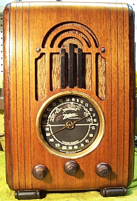 |
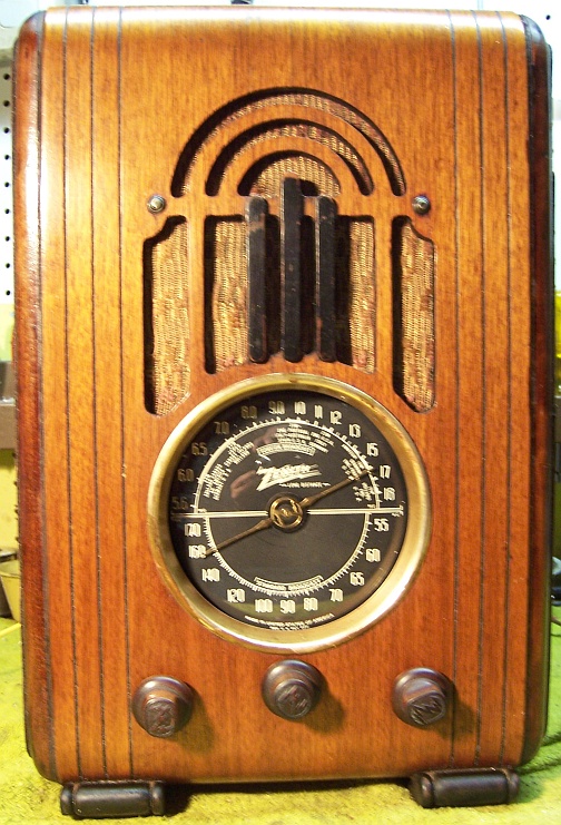
The Zenith 5S228 is a small 5-tube AC tombstone or upright
style radio. It receives the broadcast band and one short wave band. This example had seen
extensive servicing or restoration in the past, although not working. I
decided to try to reverse any previous repairs and to restore the original above and below chassis appearance to the extent
possible.
The schematic for the Zenith 5S228 can be found on Nostalgia
Air. Any part numbers will refer to numbers on that
schematic. |
My
antique radio restoration logs
Condition As Found
This radio was purchased on eBay. The cabinet was in fair original condition, as were the
knobs and grille cloth - lots or wear, dings, scratches and finish loss.
There were also fair sized veneer chips on both sides, as well as some cabinet
delamination. The
radio was sold as not working (occasional static only). In the eBay
auction listing, it was obvious that the filter
capacitor had been removed, indicating some servicing or restoration. The
cord and plug had also been replaced. I always avoid knowingly purchasing a radio that has been
restored, as many collectors take shortcuts such as removing the original capacitors and filters. I
was hoping that everything except the filter capacitor was original. Once
the chassis was removed, my worst fears were realized - every original
Zenith paper capacitor, as well as the filter capacitors, had been
replaced. All of the original resistors appeared to be in place.
Since almost all paper capacitors had been replaced, this was more likely a
collector's restoration rather than a service shop repair. Service shop
repairs usually result in only a few capacitors replaced. And in this
case, all replacements were the same type.
The seller had stated that the chassis was loose in the
cabinet. I sent a note prior to payment indicating how the chassis can be
secured (10-32 screws and fender washers). Unfortunately, the seller did not take
my advice. The packing was VERY POOR - only a single layer of small bubble
wrap around the radio, plus crumpled newspaper for padding. The seller did
stuff the inside of the radio with newspaper as I suggested. The dial
glass was shattered in shipping as a result of the poor packing and failure to
secure the chassis. No other damage was found.
Previous Repairs
-
The 6Q7G tube had been replaced by a metal 6Q7 and the tube
shield had been removed (removal of the shield is often necessary when metal
tubes are substituted for G types, since the grid cap lead may not reach the
shorter tube with the shield in place). All tubes were
replacements. All except one were the correct G types.
-
All original Zenith paper capacitor had been
replaced, all except one by Sprague Black Beauty 600 volt molded film capacitors!
That's the bad news. The good news is that guitar fans and audiophools
will pay big bucks for certain values of these capacitors on eBay. I
will obviously NOT throw any of these away!
-
The filter capacitor had been removed and tacked in tubular
capacitors installed under the chassis.
-
All resistors looked to be original.
-
The line cord had been replaced.
-
The volume control had been replaced. The original was
400K. The replacement was 500K. The shaft type and length was
correct for the radio..
-
One rivet on the 6A8G tube socket had obviously failed and
had been replaced by a 4-40 screw and nut.
-
The antenna coil shield had been removed and only one nut
was now holding it in place (the other shield attachment stud was under the
band switch and very difficult to access). Also, the antenna lead was
routed underneath the shield rather than through the hole in a rivet holding
a shield attachment stud. Also there were signs of the wave trap
capacitor having been removed and reattached to the top of the shield
(which is necessary in order to remove the shield and leave the coil
in place).
-
Several additional washers had been added to one of the
tuning capacitor studs. This was likely an unsuccessful attempt at
stabilizing the capacitor, since the grommets had deteriorated.
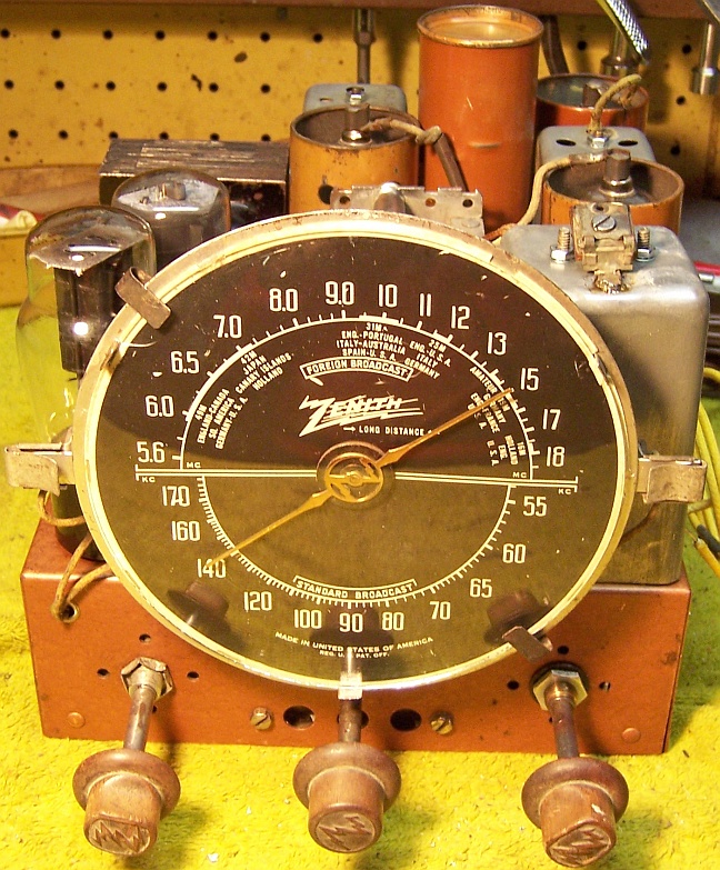
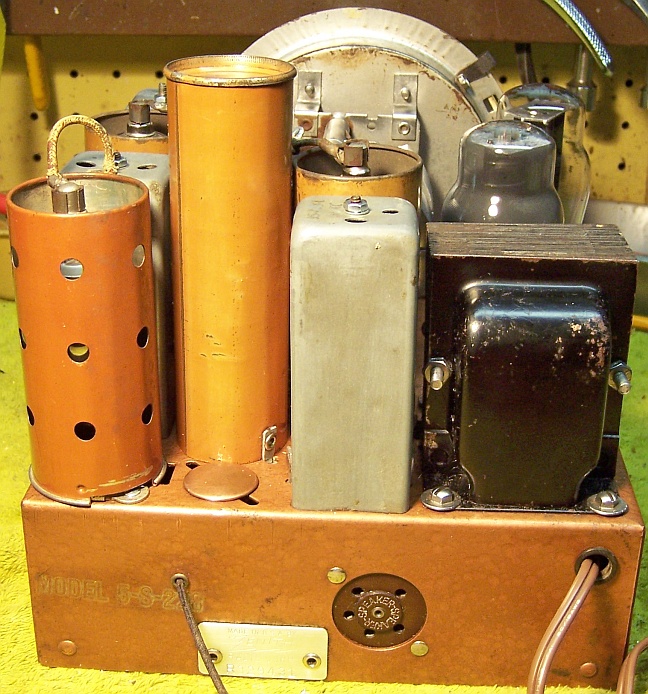
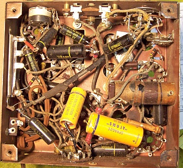
Here is the chassis as received:
Survey
My usual restoration procedure is to first make a complete
survey of the condition of all components. The survey results guide my
restoration strategy. If major or unique components are defective or
missing and
cannot be restored or replaced, I may elect to sell the radio rather than restore
it - I am not into "shelf queens".
I always assume that all paper and electrolytic capacitors are leaky and thus should be
replaced (I always "restuff" the original containers if possible).
Any mica capacitors are assumed OK until testing proves otherwise. I
did not test the radio prior to restoration - I prefer to test all components
individually rather than applying power "to see if it works".
-
The speaker field and output transformer were OK There was some damage
and a hole in the cone. The cone damage was hard to explain, since the
original grille cloth was intact, and the speaker was firmly attached to the
cabinet during shipment. Perhaps it was damaged during prior
servicing?
-
The power transformer was OK. The high voltage was balanced across the center tap (with
20 volts applied through a Variac) and power consumption was very low (about
5 watts) with full line voltage and no load.
-
The tuning capacitor mounting grommets were bad allowing excessive movement.
Almost nothing remained of the original grommets.
-
The antenna coil (part #2 in the schematic) broadcast band primary was open.
This was a potential showstopper to restoration! The remaining
windings on this coil were OK, including the wave trap.
-
The oscillator coil
was OK.
-
Both IF transformers were OK.
-
The AC switch on the volume control was OK.
-
Both pilot lamps were burned out.
-
The pilot lamp diffusers had holes burned in them (often caused by using the
wrong type of pilot lamp). But in this case #47 bulbs had been
installed. These are the correct types.
-
The dial glass was broken in shipment.
-
The insulating tubing covering the shielded lead from the tone control
capacitor to the combined band switch and tone control had deteriorated, and
had been taped to prevent shorts to adjacent wiring or components..
-
Three original resistors were out of tolerance. One was a 1 watt
dogbone, and two were 1/2 watt carbon.
-
All chassis bolts were missing, and 5/8" counter bores had been made in
the bottom of the cabinet (to accommodate shorter screws?)
-
The thick cardboard chassis mounting spacers were missing. There were
shadows on the bottom of the cabinet indicating their size.
Repairs
Antenna Coil
Before starting any repairs, I had to determine if the antenna coil (part #2)
could be repaired or replaced. If not, it made no sense to restore the
radio! The broadcast band primary winding measured open. All other
windings were OK. This could have been caused by a nearby lightning strike or
contact with an electrical line. The coil shield was removed (with some
difficulty) and the coil inspected. One worry: one of the two studs from
the shield had no nut! This was the one buried under the band
switch. It appeared that someone had removed (or attempted to remove) the
shield before. This always worries me! There was no obvious burning, damage
or broken wire visible on the coil itself. I then prepared to remove the
coil for closer inspection and repair, if possible. There were six connections on the bottom side - so careful
notes were taken before disconnection was begun. As luck would have it, the very
first lug I disconnected was the ground lug from the cold end of the broadcast
band primary winding BUT the
bus wire from the chassis ground connection was not connected to the
lug! When I measured the broadcast band primary winding from the
antenna to the cold end of the
winding, it measured 23.3 ohms! For some reason, the connection was
compromised and the coil was OK after all!
Non-Original Parts
All tubes and shields were removed. I removed the tacked in filter
capacitors. I then took
a photo of the chassis
bottom so that routing of wiring and component placement could be restored.
The replacement capacitors (as well as the original resistors) were identified
and a photo annotated with the Zenith part identifiers. In Zenith
schematics, all uses of the same part number use the same call out on the
schematic. So there may be multiple occurrences of R7 or C6 etc.
When I annotate the photo, I add a suffix making each occurrence unique.
For example R7A, R7B etc. Lead dress is often critical in radios. Since
most of the original capacitors had been replaced, I could not use their
locations for reference. Fortunately, I found photos of several chassis that had not be
hacked or heavily serviced for reference on-line at Radiomuseum
and eBay.
Cleaning
The dust was removed from the chassis using an air compressor. The dial
assembly and tuning capacitor were removed. The top of the chassis was cleaned with GoJo hand cleaner and 00 steel
wool. This process often leaves behind metal fragments which can cause
shorts, so I then went over the chassis with a small magnetic screwdriver to
retrieve them. The tuning capacitor (previously removed) was cleaned in an old Heathkit ultrasonic
cleaner with dilute ammonia.
Resistors and Capacitors
All of the replacement capacitors were removed, noting where they were connected.
Any remaining original
component wiring stubs were then removed from the terminals to confirm the connection
points. When I replace a component, I
always remove the original part (or wiring stubs left over from past component
replacement) completely from a terminal. Other
components connected at the terminal are protected from heat using old medical
clamps (hemostats). Excess solder is then removed using a solder sucker in order to
expose terminal holes for reattachment of the rebuilt or replaced component.
The Radio Museum photo and other photos found on-line provided some hints as to
original component placement. Using the Zenith parts list, I found correct original Zenith
paper capacitors to re-stuff in my stock of duds. I collect branded
(Zenith, Philco, RCA/GE, etc.) dud paper and filter capacitors just for this
situation. These capacitors were rebuilt in their original cases
using modern 630 volt film capacitors in order to restore the original
under-chassis appearance. I reseal the cardboard tubes using rosin
salvaged from servicing RCA Radiola Superheterodyne catacombs (it melts at a low temperature and will not damage
the replacement capacitors). Here
is how I restuff Zenith tubular capacitors. An AC line to ground
capacitor had been installed. That capacitor is not shown in the Zenith
schematic in Riders, so it was not replaced.
Most resistors in the set were carbon composition types, and most were 1/2
watt 20% units. Two carbon
resistors were not in tolerance and
were replaced using the same type resistor, although I was forced to use 10%
tolerance resistors. R4, a 33K 10% 1 watt dogbone type resistor, was out
of tolerance by about 50%. It was replaced by a 32K 1 watt dogbone
resistor I found in my stock that was repainted as a 33K resistor using hobby
paints. The 32K resistor measured 34.4K, which is within the 10% tolerance
required for this resistor. I collect NOS as well as used dogbone
resistors just for this purpose, and buy all I can find on eBay and at swap
meets (at reasonable prices).
The Candohm wire wound resistor was in tolerance, and its resistances were stable when terminals were moved.
Its resistances are not documented on the schematic. However a Google
search found the resistance values in an Antique Radio Forums topic.
The original filter capacitor can had been removed. I had a replacement
can in my stock, but it was not in very good shape. It was damaged in the
process of attempting to remove the original contents. After heating the case,
the contents would not budge. I had to resort to removing most of the
contents using a 1" spade bit in my small drill press. The balance
was removed using screwdrivers and other instruments (this is what damaged the
metal case). The original values
were 8mfd and 14mfd at 450 volts. I rebuilt it using two 4.7mfd 450 volt
capacitors and a 15mfd 450 volt capacitors. New wire leads were added, and
the capacitors were wrapped in strips of paper towels to hold them in
place. The capacitor was then sealed using RCA catacomb rosin.
Tubes
A 6Q7G tube replaced the metal 6Q7, and a Zenith tube shield added (1938
color was used). The remainder of the original tubes were reused (all were
good).
Other Repairs
The tuning capacitor mounting grommets were replaced by standard 5/16"
vinyl grommets. The dial drive cable (a piece of string as found) was
replaced using standard black dial cable. The existing spring and eyelets were
reused. The original gimmick capacitor on the tuning capacitor was nothing
but bare wire as found (likely originally rubber covered). It was replaced by a piece of solid insulated wire
that was wrapped around the 6A8G grid lead in the normal fashion.
The deteriorated spaghetti tubing covering the tone control wiring shield was replaced by
heat shrink tubing.
Splits and holes in the speaker cone were stabilized using GC Service
Cement. A large hole was patched using black paper from a donor speaker I
keep around just for this purpose.
The pilot lamps were replaced using #47 bulbs. The diffusers were
repaired by attaching pieces of plastic salvaged from an old ice cream carton,
which is close to the correct color. Not perfect, but it works. It
was attached toe the existing diffusers using super glue.
Testing and Alignment
Once the radio was reassembled and the tubes installed, power was brought up
slowly using a variac. AC power consumption was monitored using a watt meter, and a
DVM monitored the B+. The radio came alive with only 70 volts AC
applied. It worked on both broadcast and on short wave. I noticed
that on short wave, at quiet places on the dial, and the band/tone switch in the
treble position, a squeal would occur if the volume control was advanced to the
maximum. This could be due to altered lead dress or routing.
However, it is not an issue since one would not normally do this. The B+
measured 265 volts with only 110 volts applied (specification is 246 volts at
117 volts input). This may have been due to my using a 10mfd input filter
vs. the original 8mfd.
The set was then aligned. There were no difficulties. The IF
adjustments were way off. The broadcast band antenna trimmer could not be
peaked - the signal was still increasing at minimum capacity.
The set has excellent sensitivity for a 5-tube set, especially on the
broadcast band. Unfortunately, there was some rattle in the speaker at
higher volume levels with the treble cut and the speaker out of the cabinet. Not much I could do about this
except finding a replacement speaker or re-coning the existing speaker.
The performance was OK with the speaker mounted in the cabinet.
Restoration Results
|
Chassis Before Restoration |
Chassis After Restoration |
|
 |