Zenith 6D2615 (6-D-2615) Restoration
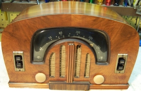 |
The Zenith 6D2615 from 1942 is a 6-tube AC/DC Superhet radio that
receives only the broadcast band. The radio had been serviced in the past but most
of the original
parts were still in place. I
decided to try and reverse all prior servicing and restore the original chassis appearance if
possible.
The schematic and a parts list for the radio can be found on Nostalgia
Air. Any part number references in the text below reference that
schematic. |
My
antique radio restoration logs
Overview
The radio was purchased on eBay. Externally it appeared to be all
original, complete and in good condition. There was a 1/2" hole in
the grille cloth. The knobs were slightly warped (typical for this radio). The
back cover was present but not firmly attached to the cabinet. The radio
features a tuned RF amplifier stage (3-gang tuning capacitor) so it should
perform well. It also features a cut down version (4 buttons) of the Zenith
Radiorgan tone control system. The circuit is quite complex, with a high parts
count. The chassis is small, and access to parts is limited and difficult.
Zenith radios of this vintage use rubber covered wiring which by now has deteriorated
and the insulation will fall off if the wiring is disturbed.
Previous Servicing
I always attempt to avoid purchasing radios that have been
"restored" by collectors or flippers, and am looking for either all
original examples or those which have been "lightly serviced" in the
distant past by radio service shops. Once I began removing capacitors for
restuffing, it was discovered that many parts had one lead cut near a terminal
then soldered back to the terminal! It is as if someone had disconnected
one lead of many capacitors for the purpose of testing the part, then
reconnecting the lead. In most such cases, the stub of the cut component
lead was still attached to the terminal and the original lead reattached with a
solder blob without securing the lead to the terminal.
-
One of the pilot lamps had been replaced. The originals were
the unusual type 1490, which are 3.2 volts at 160ma.
One lamp had been replaced with a #47, which did not work well (the original
lamp was quite dim and only one side of the dial was lighted).
-
Two paper-wax capacitors had been replaced: C3 and C12. The
filter capacitor was original.
-
All resistors appeared to be original.
-
The 35Z5G and 35L6G tubes had been replaced with GT
types. All of the remaining loctal tube types were branded Zenith and
likely original. Date codes were W2 and Y1 (1942 and 1941?) These
loctal tubes also had a "7Z" code following the date code (perhaps the
tube's manufacturer for Zenith).
-
The two dial cords had been replaced with cord that was likely
much heavier than the original cord (remnants of which were found in the
eyelets on each end of the replacement cord).
Cleaning
The chassis was very dusty, but not rusty. The dust was blown off with an air compressor.
No further cleaning was necessary.
Survey
The radio was briefly powered up through a fused variac in order
to verify the eBay seller's statement of condition. I normally do not
apply power until the radio has been restored. But in this case it was
known that the seller had plugged in the radio. It powered up OK, and
there was no reception as claimed (a lot of noise when the tuning capacitor was
moved).
In Zenith schematics, all
resistors and capacitors having the same value have the same part number call
out. So for example, there may be multiple R2's or C4's on the schematic.
Before I start work on the chassis I annotate the schematic so that all parts
have unique identifiers. I usually add an alphabetic suffix, so that the
part numbers are thus R1A, R1B, etc. I then annotate the chassis photo with
these unique part numbers with a red felt-tip pen. I then removed all
non-original capacitors, documenting their locations
and connections.
I normally measure the values of all resistors as part of the
survey process. But in the case of this radio, there are three cases where
loops exist which prevent accurate measurement of all affected resistors unless
the loop is broken. Otherwise all resistors in the loop will measure
lower than true resistance due to the shunting effect of parallel resistors. The
three loop paths are
shown below (I added a suffix "a" or "b" to indicate two
parts with the same value and part number which are unique parts in the radio):
-
R16a to R7 to R16b to R5 back to R16a. I broke the
loop by disconnecting R16b (2.2 meg) from the oscillator coil left lug (with
lead to B-).
-
R16a to R7 to R3 to R4 back to R16a (a loop within a
loop!) I broke this loop by disconnecting R3 22K from the 14Q7 tube
socket pin 5.
-
R9 to R13 to R14a to R14b to R15 back to R9. I broke this
loop by disconnecting R13 2.7K from the 14A7 tube socket pin 4.
-
The speaker field coil and cone were OK.
-
The output transformer was OK
-
The antenna, RF and oscillator coils were OK (tested for resistance and/or
continuity).
-
The IF transformers were OK.
-
The only original dogbone type resistor (R10) was out of tolerance.
All the remaining resistors were carbon composition types and all were in
tolerance!
-
All the supplied tubes were good but two were GT types vs.
the original G types.
-
The volume control and switch were OK.
-
One of the dial lamps was not the correct type (#47 vs. the
original #1490)
-
The tuning capacitor was slanted to the right and the drive
pulley (which is at AVC potential) was rubbing against the speaker frame (at B-
potential). The capacitor is only
attached to the chassis with bent-over tabs through shoulder washers in rubber
grommets, and was being pulled in that direction by the dial cord. I suspect
that this was due to deterioration of the grommets and/or replacement of the
dial cord which was very thick and likely too tight. The plates of the
tuning capacitor were also rubbing and making contact during parts of its
rotation. The scratching noises during rotation could be from the
rubbing plates or from the pulley rubbing against the speaker frame.
Restoration Strategy
Since almost all of the original parts were still in place I decided to try and
maintain the
original chassis appearance to the extent possible. All
original capacitors would be rebuilt in their original cases (restuffed),
including the original
filter capacitor. Any parts replaced in
servicing would be replaced with original parts if available. Any out of tolerance
resistors would be replaced with the same types if available. When I replace a component, I
always remove the original part completely from a terminal. Other good components connected at the terminal are protected from heat using old medical
clamps (hemostats). Excess solder is then removed using a solder sucker in order to
expose terminal holes for reattachment of the rebuilt or replaced component.
I assume that all paper and electrolytic capacitors are leaky and thus should be
replaced (I always "restuff" the original components if possible). I
do not replace mica capacitors, but may test them in place if possible (usually
this requires disconnecting one end of the capacitor).
Repairs
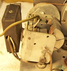
Tuning Capacitor
This is what the tuning capacitor looked like as found. It
was tilted to the right and the pulley is rubbing against the speaker
frame. The angle prevented full movement of the dial pointer. In
addition, some of the plates are rubbing and causing shorts as the pulley is
rotated. These problems were a showstopper to restoration
if they could not be repaired. Removing the capacitor was a complex and
difficult task, involving first removing the dial cord (the stringing is quite
complex) and dial assembly.
The capacitor was not attached to the chassis with the usual
bolts and nuts. There were three studs welded to the capacitor frame which
ended in tabs which were passed through a flat washer, the chassis hole grommet, and
a shoulder washer on the other side. These tabs were then simply bent over flat, and
in one case, soldered together. In order to gain access to these tabs,
several parts had to be removed (paper capacitors). The oscillator coil had to
be moved out of the way to gain access to the tabs for unsoldering and
straightening and to prevent damage to the coil. This coil is riveted to
the chassis, but the coil form can be gently pulled off its base and moved out
of the way - only one part had to be disconnected (a 220 ohm resistor). One tuning capacitor tab had
several components attached. In addition, wires from the capacitor's
stator sections had to be disconnected from the oscillator and RF coils and
pulled back through the chassis.
Once the capacitor was removed, it was discovered that many
plates were touching as it was rotated, and there was a relatively low
resistance from each stator to the frame. I first thought this was due to
dirt or debris. The capacitor was first cleaned in my Heathkit ultrasonic
cleaner and dried using a heat gun. This cured most of the problems, including
the leakage from the stators to the frame, but two sections of the capacitor
still had shorts when rotated (measured by brief flickers on my DVM).
In order to locate the shorts I connected a 9 volt battery and a
pair or antique radio earphones in series between each stator section and the
frame. This allowed me to locate where in the rotation the plates were
touching. Several plates were bent where touching in order to eliminate
the shorts. I was eventually able to eliminate all shorts, but noticed that one
of the stator sections was not firmly attached to the capacitor frame. And
if moved slightly, shorts would result. There was not much I could
do about this short of replacing the capacitor! And that would mean
finding a parts chassis - no one would go to the trouble of parting out this
radio! I will setup a search in eBay for a junker set using this same
chassis. I may get lucky at some time in the future. There was a Zenith
6R631 radio for sale on eBay (same style boomerang dial) for which the seller had posted a Youtube video of
the radio in operation. It had the same problem as mine - noise and
scratching when the tuner was rotated. It very likely had the same problem
as mine! I wound up buying this radio also, and sure enough, its tuning
capacitor was also slanted to the right and the drive pulley was rubbing against
the speaker frame, although in this case the dial cord was original. The plates of the tuning capacitor
used in these radio are VERY close
together - the three gang capacitor is very compact, and is the same size as a
typical two-gang capacitor. So all radios in this family may have these problems.
The capacitor was then reinstalled using new 5/16" vinyl grommets. All the parts that were moved or removed were then reinstalled
(the paper capacitors removed were restuffed with new axial film capacitors
before they were reinstalled). The dial cord was replaced with thinner
cord, and I made sure that excessive tension was not used for the cord driving
the dial pointer. Excessive tension in this cord likely caused the tuning
capacitor to tilt right as found.
Resistors
The radio used one older style "dogbone" type
resistor as well as carbon composition resistors. This "dogbone"
resistor (R10) was out of tolerance and would be replaced with the same type resistor.
I keep a stock of NOS and used "dogbone" resistors, and buy all I can
on eBay and at radio swap meets (when reasonably priced)! Of course, most of these resistors, even NOS resistors, have also
drifted in value and no longer have their marked values. My solution is to
find a replacement resistor of the correct value and size as measured (ignoring the
markings), and then repaint it to the needed value codes using enamel hobby
paint! In the case of this radio R10 was replaced with a 250K
1/4 watt "dogbone" resistor that now measured 442K.
It was repainted as a 470K resistor using hobby enamel paint. All the
carbon composition resistors were within tolerance.
Filter
Capacitor
The filter capacitor was a dual 20mfd @ 150 volt twist lock type
with a cardboard cover, since it is connected to one side of the power line (the
chassis itself is isolated from the power line). It was rebuilt using two 22mfd 160 volt capacitors.
After removing the capacitor from the chassis, the cardboard cover was removed.
It pulled right off without too much difficulty. In some cases I have had
to apply heat to the top of the cover using a heat gun, which melts the tar that
secures the cover. The tar was then removed from the aluminum can using lacquer
thinner, and from the cover mechanically (screwdriver). The crimp around
the base of the unit was uncrimped using an old pair of diagonal cutters.
The ground terminal ring was then removed. The insulator with two positive
terminals was then removed by prying. In this case, the contents were removed
along with the terminal board as a unit. In some cases I have had to clip
the connections between the back of the terminal board and the contents and then
remove the contents separately. In some cases, heat will release the contents
from the can. In other cases I have had to remove the contents using a
spade bit in my drill press and other tools!
The aluminum case was then cleaned. Small holes were drilled in the
terminal board close to the two positive lugs and near one of the ground lugs
(on the metal ring). I use small numbered drills that are only slightly larger
than the lead wire that passes through the terminal board. The two 22mfd 160 volt capacitors were then mounted to the
back of the terminal board. In this case I was able to use normal axial
type capacitors as there was room inside the can (in some cases radial type
capacitors must be used). Their positive leads were passed through the
terminal board and connected to the two positive lugs. A common lead was passed
through the terminal board near a ground lug but not attached until after
the capacitor was re-mounted in the chassis and the mounting lugs twisted. The
terminal board and ground lug ring were then reinstalled (there is a tab on the
ground ring which lines up with a slot in the terminal board). The crimp around
the base was restored using a small tack hammer. I did my best to smooth
things out, but the base is hidden by the cardboard cover. The cover was
reinstalled, but not secured with tar or glue for ease of future servicing.
Paper Capacitors
All except two of the original Zenith branded paper capacitors were rebuilt in their original cases
using modern 630 volt axial film capacitors in order to maintain the original
under-chassis appearance. Zenith tubular capacitors are easy to restuff.
My restuffing process for
these types is documented here. Two original Zenith capacitors had been replaced:
C3 and C12. These were replaced using the correct original Zenith duds from my
stocks, which were also restuffed. C2 (22-429AM) and C4 (22-1017AM) could not be
restuffed - they were solid wax with only a paper cover, built like Solar Seald-Tite
capacitors. They were replaced by Zenith 22-429E and 22-1017F from my dud stocks which
did have
the usual hollow cardboard tubes and wax sealed ends, and thus could be restuffed.
The suffix AM, E and F apparently indicate the manufacturer of the part.
Other Repairs
The original rubber power cord was frayed and bare wire was
exposed near the fiber chassis entrance strain relief (electrical tape had been used to prevent
shorts). The original cord was simply shortened and re-used, even though
quite stiff near the chassis (perhaps due to chassis heat?)
The one incorrect pilot lamp bulb was replaced with the correct
type (1490) which are available at 1000bulbs.com
and other vendors.
The GT type tubes were replaced with the correct types: 35Z5G
and 35L6G (both were Zenith branded).
Cabinet
The cabinet was in good shape, but was very dirty and the top had some sort of
nasty film on it (tobacco smoke or grease?} It was cleaned with GoJo hand cleaner
and 00 steel wool, followed by a coat of Johnson's Paste Wax. The film was
very difficult to remove, but the original finish looked great after cleaning. The
grille cloth was left as is. The knobs were cleaned in my old Heathkit
ultrasonic cleaner followed by soap, water, and an old toothbrush.
Testing
After the radio was completely reassembled, power was applied through a
wattmeter and fused Variac. Power was brought up slowly while monitoring
the B+ voltage and the wattmeter. The radio came alive and worked - no assembly errors! The radio was then
aligned. The IF transformers were very close to correct. The other
trimmers were far off, but these had been disturbed during the tuning capacitor
cleaning. The volume control was slightly scratchy, but responded to a spray of
GC Big Bath. The tuning capacitor turned out perfect - no plates were rubbing,
and no noise. The radio was quite sensitive. The tone controls
worked well. However, there was some speaker rattle and distortion or muddiness
on low
bass on certain stations. I have had this same problem on other Zenith
radios. Perhaps there was less bass when these radios were designed? There
was no obvious problem with the speaker cone. It just appeared to be
excessive cone excursion. The solution is to simply depress the BASS tone button
or to reduce the volume when this happens. Some collectors have modified
the tone control circuit to reduce this tendency.
Restoration Results
Most of my restoration objectives were met, but not all. There was no
intention of restoring the set to factory new appearance! My objective is
usually to reverse any prior servicing and make the radio appear to have never
been repaired. I do not go so far as to artificially "age"
solder joints, as do some collectors! Nothing gives away a restoration
faster than bright and shiny solder joints. Here are some of my
"misses":
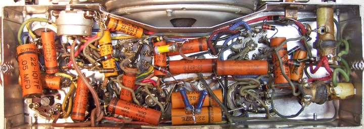
- Two original Zenith paper/wax capacitors could not be restuffed since
they were solid wax with only a thin paper cover. These were two of the
lighter colored capacitors seen in the before restoration photo
below (far left and far right). These
all had a manufacturers code of AM. They were replaced using original Zenith
duds with the same part number (22-xxx) and value but with a manufacturing
code other than AM such as C, E, or F. Zenith used a variety of
component sources, and especially in 1942 near the close of domestic
manufacturing for many vendors. So this substitution is legitimate.
- The original screws that held the back cover (slotted washer head wood
screws) were missing. Two had been replaced by normal round head
screws plus cup washers, and two were missing. I will keep a lookout
for two more similar cup washers and screws so that at least the four all
match.
Chassis Before and After Restoration
Before
|
 |
After
|
 |
Cabinet Before Cleaning (eBay photo)

Restoration Complete


