Zenith 6D413 (6-D-413) Restoration
 |
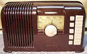
The Zenith 6D413 from 1940 is a 6-tube (5 tubes plus ballast
tube) AC/DC Superhet
circuit radio that
receives only the broadcast band. At first glance, the radio had seen no obvious servicing
(other than tubes) in the past and all
of the original
parts appeared to be still in place. I
decided to try to restore the the radio and maintain the original chassis appearance if
possible. The model number was not confirmed, since there was no model
number or chassis number found - only a serial number tag.
The schematic and a parts list for the radio can be found on Nostalgia
Air. Any part number references in the text below reference that
schematic. |
My
antique radio restoration logs
Overview
According to an excellent article found at http://www.uv201.com/Radio_Pages/zenith_bakelite.htm,
in 1940 Zenith introduced a line of radios that featured a molded bakelite
chassis. The chassis was mounted upside down in the cabinet and the tube
sockets, volume control, one IF transformer, trimmers as well as some fixed mica
capacitors, and other
components were molded as integral parts of the chassis. These radios were
troublesome from day one, and they were almost impossible to work on. Most
were recalled and destroyed. These models only lasted one year, and I'm
sure some heads at Zenith did roll for this blunder!
My example was purchased on eBay and listed as not tested/not
working. The AC line cord had been cut off. Externally it appeared to be all
original, complete and in excellent condition. There were no cracks or breaks
in the cabinet. The chassis is
small and quite compact, and access to parts is limited and difficult. There
are hair thin wires exposed under the chassis coming from the first IF transformer
and from the oscillator coupling coil. These components have few or no
terminal lugs, and wire ends from the windings are connected to other points on
the chassis. Damage is possible unless extreme care is taken.
I had previously restored a Zenith
model 4K-402D, a four-tube battery portable that uses the same bakelite
chassis construction.
Prior Servicing
I always attempt to avoid purchasing radios that have been
"restored" by collectors or flippers, and am looking for either all
original examples or those which have been "lightly serviced" in the
distant past by radio service shops. In this example, almost all of the original
parts were still in place. The only non-original parts I found were
one resistor, some of the tubes, and the pilot lamp. The 35Z5G and 35L6G tubes had been replaced with GT type
tubes. The 12A8G, 12K7G, and 12Q7G tubes were all the correct types, were
branded Zenith and were
good. The 12K7G and 12A8G were date code "X 9Y" (1939?) and likely
OEM. The 12Q7G was
date code M0R, indicating 1940 and a replacement. The ballast
tube was an Amperite, and possibly original.
Survey
My usual restoration procedure is to first make a complete
survey of the condition of all components. The survey results guide my
restoration strategy. I never apply power to a radio before
restoration. If major and unique components are defective or missing and cannot
be restored or replaced, I may elect to sell the radio rather than restore it.
I always assume that all paper and electrolytic capacitors are leaky and thus
should be replaced (I normally "restuff" the original containers if
possible). Survey results:
-
All tubes tested good.
-
The speaker was OK.
-
The output transformer was OK
-
The filter choke was OK
-
The oscillator coil and oscillator coupling coil were OK
-
The IF transformers were OK.
-
The dial lamp was OK but was the wrong type (#44 vs. #47)
-
The line cord was had been removed and the fiber entry board
was broken.
-
One resistor, R4 (2.2 meg) had been replaced by a 170K
resistor - old style dogbone resistor! This was likely an older
repair. I'm not sure what effect this change would have had to the
performance. R8 (470K) was 36% high. All other resistors were
OK.
-
The AC switch and volume control did not operate
correctly. This was likely what killed the radio, since no other
serious problems were found. If this issue could not be resolved, it would
be a showstopper!.
Restoration Strategy
Since almost all of the original parts were still in place I decided to try and
maintain the
original chassis appearance to the extent possible. All
original capacitors would be rebuilt in their original cases (restuffed). Any parts replaced in
servicing would be replaced with original parts if available. Any out of tolerance
resistors would be replaced with the same types if available. When I replace a component, I
always remove the original part completely from a terminal. Other good components connected at the terminal are protected from heat using old medical
clamps (hemostats). Excess solder is then removed using a solder sucker in order to
expose terminal holes for reattachment of the rebuilt or replaced component.
I assume that all paper and electrolytic capacitors are leaky and thus should be
replaced (I always "restuff" the original components if possible). I
do not replace mica capacitors, but may test them in place if possible (usually
this requires disconnecting one end of the capacitor).
Repairs
Volume Control and Switch
The volume control and switch assembly was unique to this type
of radio and cannot be replaced by the usual type of replacement control. Key
portions of the control, such as the housing and shaft bushing, are actually molded as part of the chassis! My
IRC Replacement Volume Control reference manual states "Obtain replacement
from manufacturer." The volume control element has only a thin layer of
carbon and is thus easily damaged. The rotating element does not contact the
resistance element directly. Rather, there is a thin flexible circular steel spring that is compressed against the resistance track by the
rotating element. As found, there was a bent or indented area found on the circular
spring. In addition, the control shaft was not securely attached to the rotating
element. It appeared originally to have been pressed in. This
allowed the control shaft to rotate continuously. Since the shaft also
operates the AC switch, this would have to be repaired somehow.
The carbon resistance element measured a reasonable resistance
of 545K (spec is 500K), although there were obvious areas of wear and damage. My
first attempt was to repair the control, since replacement would have been
impossible. The rotating member and some fiber washers were removed
for access to the circular spring by removing a clip on the top of the chassis. The kink
in the contact spring was straightened as best I could using flat nose pliers.
The underside of the contact spring was cleaned using lacquer thinner and a
Q-tip. The carbon resistance track was NOT cleaned. I have learned the
hard way that any attempt to clean this type of control will destroy the
resistance element. The control shaft and rotating member were reattached by
soldering them together. The control was then reassembled and tested. It
was tested by connecting a 9 volt battery across the resistance element and measuring the
voltage on the center lug using an analog VTVM as the control shaft was rotated.
There was a dead area in the rotation, and the VTVM pointer jumped around. So the control would somehow have to be
replaced.
The switch mechanism was originally a set of spring contacts
attached to the bakelite chassis that were operated by a cam molded on the
bottom of the volume control knob. After taking some measurements, I
determined that there was not enough room to mount a normal type volume control
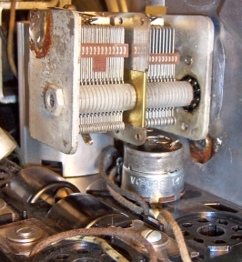
with an attached switch. There was only about 7/8" clearance between the top of the
chassis and the tuning capacitor. There were only a couple of options that I
could think of:
-
Install a normal IRC type Q (or equivalent) 500K volume control on the top of the
chassis without an attached switch and install a switch in the AC line
cord. Even this could be a problem since the normal shaft provided
with IRC type Q-controls may not be compatible with the volume control knob.
-
Search my junk box of controls for a more suitable replacement
control with switch that will fit and which has the correct length split-splined shaft.
I have a collection of used controls with and without switches
from scrapped radio and TV chassis, or purchased at swap meets. I did find a couple of candidates that
might fit, but just
barely! Both were 500K and tested good after cleaning. Both had split-splined
shafts. One shaft was slightly longer than the other. In order to use this
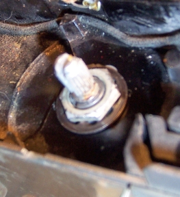
strategy, I had to remove the existing control shaft bushing and also enlarge
the chassis hole to 3/8". The chassis is quite thin at this point, so
this was a dangerous operation. The tuning capacitor and dial assembly was
removed for access. I was able to enlarge the hole to clear
the replacement control using a set of progressively larger drill bits.
The shaft bushing on top of the chassis and the short bakelite boss on the other side of the chassis
were removed using
a Dremel tool and cut-off disc as a grinder. Both replacement candidate
controls were mounted and checked for fit. I had to cut off most of the AC switch
lugs in order to clear the tuning capacitor rotor directly above the control.
The knob was refitted to check for the best shaft length.
The replacement control seemed to work OK, but compromises were
required. First, since the replacement control was mounted on TOP of the
chassis, the direction of rotation (minimum to maximum volume) was opposite of
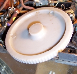
the original control. Since the control is operated by a thumb wheel
rather than a knob, this is not a major issue. Also, the three terminal lugs
(now on TOP of the chassis) are in the opposite order from the original, and
also on the other side of the chassis. So some rearrangement of wiring was
necessary.
At this point I abandoned my original objective of restoring
the original chassis appearance and decided to simply get the radio working.
Resistors
The radio used some older style "dogbone" type
resistors as well as 20% tolerance carbon composition resistors. IR4 (2.2 meg) and R8 (470K) were both 1/4 watt dogbone types, and were
replaced with normal 1/2 watt carbon composition types. Fortunately all of the wire wound resistors in the radio were
OK.
Wax/Paper Capacitors
All except one of of the original Zenith paper capacitors were replaced with
modern axial 630 volt film capacitors. The placement of the original capacitors
were very critical since there is very little space under the chassis. They were
not restuffed. One metal cased capacitor was above the chassis and thus
visible. This one was restuffed.
Filter Capacitor
The original tubular filter capacitor was still in place. It was
a three section capacitor with wire leads. The original tubular capacitor was
removed from its metal case, but the original wire leads were retained and
re-used. New axial electrolytic capacitors were used to replace the original
capacitor. They were insulated using shrink tubing and re-installed in the
original metal container.
Other Repairs
The line cord was replaced by a modern brown vinyl cord.
Testing and Alignment
Once the radio had been reassembled and the tubes installed,
the radio was powered up using a fused Variac. The radio came alive and
actually worked. The set was then aligned. The radio worked, but the
performance was nothing to write home about. Based on my experience with
this radio and my Zenith 4K-402D, I
will certainly avoid buying any more of this type of radio!
Restoration Results


