Zenith Model 6G038R (6-G-038R) Restoration
 |
The Zenith model 6G038R (6-G-038R), 1946 model year, is a
large tabletop 6-tube superhet circuit radio that operates from AC, DC or dry batteries. This example had seen
extensive servicing in the past. I
decided to reverse previous repairs to the extent
possible.
The schematic for the Zenith 6-G-038R can be found on Nostalgia
Air. Any part numbers in this log will refer to numbers on that schematic. |
My
antique radio restoration logs
Overview
This radio uses 1.5 volt battery tubes although it can operate
on 117 volts AC or DC. The radio's large cabinet accommodates the
battery, which supplies 9 volts for the tube filaments and 90 volts for
B+. It receives the standard broadcast band and two short wave bands and has
the Zenith Radiorgan tone
control system. The circuit is similar to Zenith Transoceanic and
suitcase style portable radios, however instead of a Wavemagnet (loop antenna) this radio uses an
extendable whip antenna (Waverod) for local stations and can accommodate a long wire outdoor antenna.
The circuit is quite complex due to the fact that all the filament type tubes
are in series, which complicates the proper biasing and AVC operation.
Also, lots of bypass capacitors are needed to prevent tube interaction and
feedback. The small compact chassis and high component count makes
servicing difficult.
Previous Repairs
-
None of the tubes were branded Zenith, and thus were likely
all replacements. The 1A7G tube had been replaced by a 1A7GT, with the
taller tube shield left in place.
-
Several pieces of wiring had been replaced.
-
The dial cord had been replaced - the tension spring looked
original.
-
The dial drive shaft friction spring had been replaced.
-
The black fiber washer that belongs between the dial pointer
and the dial scale was found on the bandswitch shaft!
-
A filter capacitor had been tacked in across the first
filter capacitor section C36. The two original filter capacitor cans were
still in place.
-
One paper capacitor had been replaced.
-
For some reason, a 0.25mfd/600 volt bypass capacitor had
been tacked in across the existing .05mfd AVC bypass capacitor C8 connected
to lug 5 of RF coil L1. C8 had NOT been removed. This would
surely have screwed up AVC action.
-
Power resistor R12 had been replaced by a 150 ohm 10 watt
unit (the original was 2.5 watts - I'm not sure what it might have looked
like).
-
There were signs that the volume control and associated
tuning hardware had been removed and replaced - I'm not sure why! Perhaps to
replace the dial cord? The volume control was original. But some of the wiring to the control had been spliced.
-
The 1LD5 first audio tube plate load resistor R15 had been
replaced with a 5 megohm dogbone type resistor (should be 1 meg) - the radio
could not have worked very well after that! All the other resistors
looked to be original.
-
The power cord and plug had been replaced
-
A replacement plastic attachment had been fabricated to hold
one of the Radiorgan panels to the escutcheon. Perhaps the original
had broken off. This attachment was not visible from the front.
Original Condition
The radio had been purchased on eBay. It was said to be
working. I did not test it, since all the capacitors were likely original and
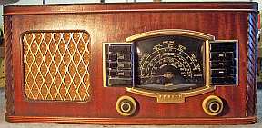
thus leaky, and the tube filaments are very fragile. The cabinet had been refinished and the escutcheon and
speaker grille painted gold. The grille cloth looked original and was in excellent
condition (it looked like the example found at Radio
Museum). The knobs were original and in
excellent condition with minimal warping. The dial glass was intact, and the dial
glass rubber extrusion was still in good condition (it may have been replaced).
Most,
if not all the rubber covered wiring was still supple and in great condition -
including most of the leads to the Radiorgan tone control switch panels - again, very
unusual. The chassis was quite dirty, but not rusty. All tube
shields were still in place.
Survey
I NEVER apply power to a radio "to see if it
works", even with a Variac or "dim bulb tester". My usual restoration procedure is to first make a complete
survey of the condition of all components. The survey results guide my
restoration strategy. If major and unique components are defective or
missing and
cannot be restored or replaced, I may elect to sell the radio rather than restore it.
I always assume that all paper and electrolytic capacitors are leaky and thus should be
replaced (I always "restuff" the original containers if possible).
Any mica capacitors are assumed OK until testing proves otherwise.
It was interesting that a handful of paper capacitors in this
radio were Aerovox and Solar branded without Zenith part numbers. All Zenith
radios that I have worked on had either Zenith branded capacitors, or else other
brands which had Zenith part numbers (22-xxx). The non-Zenith capacitors
appeared to be original based on examination of the associated solder joints and
the difficulty of access for servicing. Inquiries on Antique
Radio Forums yielded opinions that in 1946, right after WWII, when this
radio was made, manufacturers were scrambling for parts, and might have used
whatever was available at the time, even if not branded Zenith. This may
also have applied to the tubes, none of which were branded Zenith in this radio
(but could have been original for the same reason).
-
The output transformer was OK.
-
All RF and IF
coils and transformers were good.
-
The tuning capacitor mounting grommets were OK.
-
The chassis washers were hardened and crumbling.
-
Almost all of the rubber covered wire was surprisingly OK - very unusual.
Only one lead was crumbling, but one lead to the right Radiorgan tone
control panel was shorting to the shield (all three leads inside the braided
shield were replaced).
-
The power cord was OK (rubber or vinyl) but was likely not original
(apparently had been shortened).
-
Resistor R19, an 870 ohm 1 watt wire-wound MicaMold type, was open.
-
Candohm resistor
R13-R14 was OK.
-
Four resistors were out of tolerance. Two were 1/4 watt dogbone types.
The remainder were 1/4 watt carbon composition types.
-
All the tubes were good.
Repairs
I first removed the tacked-in filter capacitor, the non-original paper
capacitors, and the non-original R12. All tubes and shields were removed.
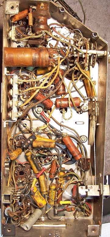
The tuning capacitor was removed for cleaning access to the chassis. I then took photos of the chassis
bottom so that routing of wiring and component placement could be restored.
Lead dress is often critical in radios. When I replace a component, I
always remove the original part completely from a terminal. Other
components connected at the terminal are protected from heat using old medical
clamps (hemostats). Excess solder is then removed using a solder sucker in order to
expose terminal holes for reattachment of the rebuilt or replaced component.
The top of the chassis was cleaned with GoJo hand cleaner and 00 steel
wool. The tuning capacitor was cleaned in an old Heathkit ultrasonic
cleaner with dilute ammonia. After drying, the bearings were lubed with
automotive distributor cam grease.
The Radiorgan tone control contacts were cleaned in my old Heathkit
ultrasonic cleaner, using dilute ammonia. Only the switch contacts were
cleaned, and were carefully rinsed and dried afterwards.
The dial drive cord was replaced with a more suitable black dial cord
material. The original spring was re-used.
Resistors and Capacitors
In most Zenith schematics, all parts which have the same value or type have
the same reference number. For example, there may be multiple occurrences
of R1 or C2. Before starting restoration, I normally add a suffix forming
unique identifiers: R1A, R1B, etc. That way I can make the correct
reference in my notes. I usually also annotate the under chassis
photograph with the parts callout.
All the original Zenith paper capacitors were rebuilt in their original cases
using modern 630 volt film capacitors in order to maintain the original
under-chassis appearance. Here is the process I
use. I reseal the cardboard tubes using rosin
salvaged from RCA catacombs (it melts at a low temperature and will not damage
the replacement capacitors. The non-Zenith bypass capacitors were
replaced with Zenith duds having the correct Zenith part number, which were then
restuffed with new 630 volt film capacitors.
In preparation for restuffing the filter capacitors, I removed the cardboard cover from a Zenith 22-1047C (10+20+30mfd @ 150 volts). Underneath, the metal can was labeled
PHILCO 61-0089, which was a 15+10@350, 20@25! I can only assume that Zenith's capacitor
supplier (who also supplied Philco) had a surplus of these aluminum cans and
used them to make the needed Zenith part. The can would not be visible since there was a cardboard cover.
Just guessing that this and other things went on during the restart of manufacturing in 1946 after the war, when supplies and parts were likely scarce.
Both filter capacitors were removed from the chassis and restuffed to
preserve the chassis appearance. The original cans were restuffed using the
following technique:
- The cardboard covers were removed by heating with a heat gun to soften the
tar which retained them.
- The crimp around the base was uncrimped using several tools, such as
diagonal cutters and small screwdrivers.
- The terminal board was removed after the aluminum leads connecting the terminals to the body of the capacitor were
cut. The stubs were then cut flush with the bottom of the terminal
board.
- The old contents were removed.
- The old can was cleaned out.
- Holes were drilled through the terminal board close to
the terminals.
- The new components were installed inside the old can. Leads for the
common ground and positive leads were routed through the drilled holes
and attached to the original terminals (later secured by soldering when the
original leads were reattached). I use radial type electrolytics to
save space. Capacitor C36-C37-C38 (10+20+30@150 volts) was restuffed
using 10, 22, and 33mfd @160 volt capacitors. Capacitor C27-C28
(200@10 volts, 40@150 volts) was restuffed using 220@10 volts and 47@160
volt capacitors.
- The terminal board was reinstalled and the crimp on the base restored.
- The cardboards covers were reinstalled, but not cemented in place for ease
of future servicing.
- The original retaining rivets had failed. The capacitors were
secured to the chassis using aluminum pop rivets.
The non-original R15 was replaced using a 1 megohm 1/4 watt 20% carbon
composition resistor I found in my resistor stock. It measured very close
to1 megohm, and was likely the same type as the original used. The non-original
R12 was replaced by a new 140 ohm 3 watt wire-wound resistor. It was very
small and hardly visible unlike the 10 watt unit replacement originally installed (the
original was a 2.5 watt "Zipohm", whatever that is!) R19,
originally a 870 ohm 1 watt wire wound Micamold type, was replaced by a new 860 ohm 1 watt wire-wound
resistor that was epoxied into a depression cut into the back of the original
resistor. The original leads were cut off. The resulting repair is not
visible from the top.
Two 2.2meg dogbone resistors were replaced with 1/4 watt dogbone
resistors that had drifted close to the needed values. These were
repainted as 2.2meg using hobby paint. All the other resistors needed were
1/4 watt carbon composition types (new stock is available, but differs in
appearance from the originals).
Testing and Alignment
Once the radio was reassembled and the tubes installed, power was brought up
slowly using a variac. Two DVMs monitored the B+ and the critical filament voltage. The
radio worked immediately on both broadcast and both short wave bands. The Radiorgan
controls worked correctly. There was a slight rattle in the speaker at
high volumes or high bass levels. With 120 volts input, the B+ was
correct,
but the filament voltage was low (8.4 volts vs. 9 volts). This may be due
to the fact that Candohm resistor R13-R14 was about 10% high in value, which
would decrease the filament voltage. It also may be normal, since the
filament voltage is not indicated in the Riders documentation. Since the radio works OK, I decided to leave well enough alone!
The set was then aligned. I initially set the dial pointer so that the
position at each end was about equal. However, at this position, the broadcast
band could not be set to scale with the broadcast band trimmer as loose as
possible. So I had to move the pointer backwards a
small amount to get the radio to track on the high end of the broadcast band. The high
short wave band tracked OK, but the police band could not be set to scale (it
was close with the trimmer all the way out). The radio was not that
sensitive using only the Waverod antenna. However, we are in a rural
area. Performance with a short wire antenna was excellent on all bands. The
radio was not tested in battery mode.
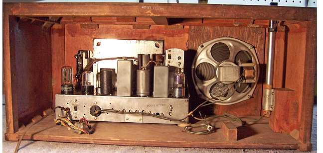
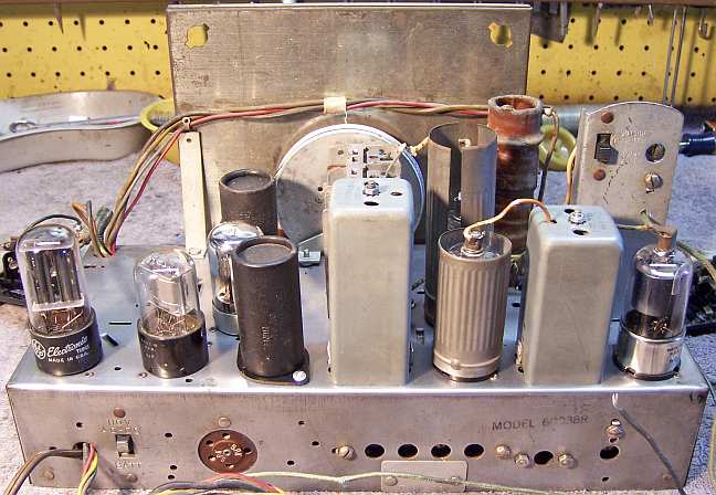
Restoration Results
|
Chassis Before Restoration |
Chassis After Restoration |
 |
 |