Zenith Model 6G038R (6-G-038R) 2nd Restoration
 |
The Zenith model 6G038R (6-G-038R), 1946 model year, is a
large tabletop 6-tube superhet circuit radio that operates from AC, DC or dry batteries. This
is the second example of this radio that I have restored. This example had seen
minimal servicing in the past. The cabinet in this example was not as good
as the first one I restored, but had its original finish (the first example had been
refinished). The chassis in this example was almost original.
The schematic for the Zenith 6-G-038R can be found on Nostalgia
Air. Any part numbers in this log will refer to numbers on that schematic. |
My
antique radio restoration logs
Overview
This radio uses 1.5 volt battery tubes although it can operate
on 117 volts AC or DC. The radio's large cabinet accommodates the
battery, which supplies 9 volts for the tube filaments and 90 volts for
B+. It receives the standard broadcast band and two short wave bands and has
the Zenith Radiorgan tone
control system. The circuit is similar to Zenith Transoceanic and
suitcase style portable radios, however instead of a Wavemagnet (loop antenna) this radio uses an
extendable whip antenna (Waverod) for local stations and can accommodate a long wire outdoor antenna.
The circuit is quite complex due to the fact that all the filament type tubes
are in series, which complicates the proper biasing and AVC operation.
Also, lots of bypass capacitors are needed to prevent tube interaction and
feedback. The small compact chassis and high component count makes
servicing difficult. This type of radio was often purchased by rural
customers who currently had no electrical service. They could use the
radio on (expensive) batteries and not have to purchase a new radio when
electrical service arrives.
Previous Repairs
-
Only one of the tubes (3Q5GT) was branded Zenith, and thus most were likely replacements.
-
The dial cord had been replaced (spliced) - the tension spring looked
original. The dial cord had been wound in the wrong direction on the tuning
shaft, which must have confused the operator since the dial pointer would
rotate in the opposite direction as the tuning knob!
-
All resistors and capacitors appeared to be original.
-
The 1A7G tube had been replaced by a 1A7GT and the required tall tube
shield was missing (in my first restoration of this same model, the tall
shield was still in place but a 1A7GT tube was installed).
-
The original chassis bolts had been replaced by self-tapping screws
and washers. The chassis must have been removed in order to replace
the dial cord, and perhaps the original chassis bolts had not been replaced.
Original Condition
The radio had been purchased on eBay. It was sold as not working.
The cabinet finish was original, but had some rather serious scratches, dings, finish wear and oxidation (it was quite dark). The grille cloth
was original and was in excellent
condition The knobs were original and in good condition with minimal warping. The dial glass was intact, and the dial
glass rubber extrusion was still intact, although I'm sure it would crumble if
disturbed! Several cabinet
glue blocks
had broken loose, likely due to rough handling in shipping. Some of the rubber covered wiring was still supple and in great condition -
including the leads to the Radiorgan tone control switch panels - very unusual.
The battery cable had some leads that would have to be replaced. The chassis was quite dirty, but not rusty.
The insulation on the rubber covered wiring under the chassis would fall off,
exposing bare wire, if moved even the slightest amount. Every effort was made to
retain the original wiring where possible.
Survey
My usual restoration procedure is to first make a complete
survey of the condition of all components. The survey results guide my
restoration strategy. If major and unique components are defective or
missing and
cannot be restored or replaced, I may elect to sell the radio or keep it for
parts rather than restore it.
I always assume that all paper and electrolytic capacitors are leaky and thus should be
replaced (I always "restuff" the original containers if possible).
Any mica capacitors are assumed OK until testing proves otherwise.
It was interesting that a handful of paper capacitors in this
radio were branded Aerovox or Solar without Zenith part numbers. This was
also true in my first example of this radio. All other Zenith
radios dated after about 1932 that I have restored had either Zenith branded capacitors, or else other
brands which had Zenith part numbers (22-xxx). The non-Zenith capacitors
appeared to be original based on examination of the associated solder joints. Inquiries on Antique
Radio Forums yielded opinions that in 1946, right after WWII when this
radio was made, manufacturers were scrambling for parts, and might have used
whatever was available at the time, even if not branded Zenith. This may
also have applied to the tubes, since only one was branded Zenith in this radio
(but could have been original for the same reason).
-
The output transformer was OK.
-
One primary winding of the antenna coil (the 23 ohm winding) was open - a
potential showstopper! The detector coil and oscillator coil were OK.
-
The IF transformers were OK.
-
The tuning capacitor mounting grommets were intact, although hardened and
thus providing no cushioning.
-
The chassis washers were hardened and crumbling.
-
The rubber covered wiring to the Radiorgan tone panels was OK, but the
battery cable had several frayed leads that would have to be replaced (even
though I did not plan on using batteries).
-
The power cord was original and falling apart - it would have to be
replaced..
-
Candohm resistor
R13-R14 was OK. Originally one section was 21% high. I applied
my standard Candohm "fix", which is to squeeze the metal case near
each terminal using a small C-clamp. The insulation for this resistor looked to
be in good condition, so the resistor was left in place. After the
squeeze, both sections were in tolerance and one section almost exact.
-
R12 (140 ohms, 10%, Zipohm) was out of tolerance. When later examined, it
was broken and would have to be replaced. The original was a thin flat sand
type resistor (this resistor already had been replaced in my first example of this
radio).
-
Six resistors were out of tolerance. Three were 1/4 watt old style dogbone types.
The remainder were 1/4 watt or 1/2 watt carbon composition types.
-
Four of the tubes were bad - they had open filaments and shorts. Only the 117Z6GT
and 3Q5GT (Zenith) were good..
Antenna Coil
Before starting restoration I had to deal with the potential showstopper
issue with the antenna coil, which had an open primary winding (the one used with
an outside antenna). The coil was covered with dirt and dust which was
imbedded in the wax coating. So it was not obvious which of the multiple
coils was open. So I decided to remove the coil from the chassis for
closer inspection and possible repairs or rewinding. This was a very
difficult task, since the terminals of the coil under the chassis, as well as
the mounting studs, are under the band switch! I started disconnecting
wiring and other components from the lugs, while making careful notes about wire
colors and where each wire was routed. Some thicker bus wiring as well as
one capacitor lead was cut rather than unsoldered in order to prevent possible
damage to the coil, or if there was no room for a soldering iron! The capacitor would have to be removed and restuffed
anyway. The bus wiring and capacitor would be replaced (reattached to the coil terminal)
before the coil was re-installed. It is easier to reattach some leads or
components if they are attached before the coil is fully fastened to the chassis
(while hanging in mid air).
Once removed from the chassis, the coil was heated using a heat gun to remove
most of the wax and dirt. I simply let the wax drip into a puddle on a piece of
newspaper. The primary winding that was open was located. It was the
very top winding, and was bank wound. The break was found at the point where the
inside (start) of the winding was routed over the top of the coil form and then
down to a terminal on the bottom of the coil form. This left about 3/8" if wire available
for a splice - very little room for error! A piece of #28 solid bus wire was routed from the
bottom terminal up inside
the coil form to a small hole drilled near the primary winding stub. The
stub was carefully scraped clean of enamel and tinned, then attached to the solid
wire. Measurements of all windings now indicated the coil was OK. I then
melted the puddle of original wax left and poured it onto the coil, and then
smoothed it out as best I could using my heat gun. The coverage was not as
thick or uniform as it was originally, since I did not have enough wax to dip the coil.
Repairs
Before starting any repairs I took photos of the chassis top and bottom so that routing of wiring and component placement could be restored.
Lead dress is often critical in radios. When I replace a component, I
always remove the original part completely from a terminal. Other
components connected at the terminal are protected from heat using old medical
clamps (hemostats). Excess solder is then removed using a solder sucker in order to
expose terminal holes for reattachment of the rebuilt or replaced component.
The tuning capacitor and the two
filter capacitors were removed for cleaning access to the chassis. The filters
later would be restuffed. The top of the chassis was cleaned with GoJo hand cleaner and 00 steel
wool. The tuning capacitor was cleaned in my old Heathkit Ultrasonic
cleaner after removing the trimmer hardware and mica insulators. The
capacitor was then cleaned using soap, water, and toothbrushes. In order
to return the trimmers to near their original positions, before removing the
screws I noted the original position of the screws (on the clock) and how many
half-turns (and fractions) to completely tight. Once the cleaning and
drying was completed, the trimmer hardware was reinstalled and the trimmer
screws returned to where they were by fully tightening the screws then backing
off the documented number of half-turns and fractions. I like to get them
close to where they were originally before alignment. After drying, the bearings were lubed with
automotive distributor cam grease.
The Radiorgan tone control contacts were cleaned in my old Heathkit
ultrasonic cleaner, using dilute ammonia. Only the fixed and moving switch contacts were
cleaned, and were carefully rinsed and dried afterwards.
The dial drive cord was replaced with a suitable black dial cord
material. The original spring was re-used.
The power cord was replaced using a modern brown vinyl cord with molded
polarized plug (the original was brown rubber with a molded plug). Replacement tubes were installed for the four defective
tubes. The blue and black leads in the battery cable were replaced.
The remaining two were OK.
Resistors and Capacitors
In most Zenith schematics, all parts which have the same value or type have
the same reference number. For example, there may be multiple occurrences
of R1 or C2. Before starting restoration, I normally add a suffix forming
unique identifiers: R1A, R1B, etc. That way I can make the correct
reference in my notes. I usually also annotate the under chassis
photograph with the parts callout.
All the original Zenith branded paper capacitors were rebuilt in their original cases
using modern 630 volt axial film capacitors in order to maintain the original
under-chassis appearance. Here is the process I
use. I reseal the cardboard tubes using rosin
salvaged from servicing RCA Radiola superhet catacombs (it melts at a low temperature and will not damage
the replacement capacitors). The paper capacitors that were not
Zenith branded were replaced with Zenith duds having the correct Zenith part
number. These were also restuffed with new 630 volt film capacitors. I collect Zenith and other
branded capacitors (Philco, RCA, GE etc.) just for this situation, and also to
reverse any prior servicing where original parts have been replaced. Since all
capacitors listed in the parts list had Zenith part numbers, I assumed that
later examples of this radio would have all Zenith capacitors, once the post-war
parts shortage was alleviated.
Both original filter capacitors (C36-C37-C38 and C27-C28) were restuffed to
preserve the chassis appearance. The original cans were restuffed using the
following technique:
- The cardboard covers were removed by heating with a heat gun to soften the
tar which retained them.
- Excess tar was removed from the insides of the covers mechanically, and
cleaned from the outside of the inner metal cans using lacquer thinner.
- The crimp around the base was removed using several tools, such as
diagonal cutters and small screwdrivers.
- The ground lug ring was removed.
- The three layer terminal board assembly was removed intact after the aluminum leads connecting the terminals to the body of the capacitor were
cut. The stubs were then cut flush with the bottom of the terminal
board and the board cleaned using lacquer thinner. The assembly
consists of two fiber insulators separated by a rubber-like gasket material.
- The old can contents were removed by pulling on the projecting stubs.
Sometimes more aggressive methods are necessary if the contents are tightly
packed or are firmly attached with tar.
- The old can was cleaned out mechanically (the cans do not need to be
totally clean inside).
- Holes were drilled through the terminal board close to
the terminals as well as close to one of the ground lugs. The ground lug
ring was temporarily aligned with the terminal board so that the proper
location for a common ground lead could be determined. There is a
projecting tab on the ground lug ring which matches up with a notch in
the terminal board.
- The new components were installed inside the old can. Leads for the
common ground and positive leads were routed through the drilled holes
and attached to the original terminals (later secured by soldering when the
original leads were reattached). I use radial type electrolytics in
order to
save space. Thin insulating spaghetti tubing was used where needed to
prevent shorts. Capacitor C36-C37-C38 (10+20+30@150 volts) was restuffed
using 10, 22, and 33mfd @160 volt capacitors. Capacitor C27-C28
(200@10 volts, 40@150 volts) was restuffed using 220mfd@10 volts and
47mfd@160
volt capacitors. On the parts list, C27 was listed as 200mfd @ 10
volts. On the actual capacitor case C27 was listed as 20 volts. The
capacitor I installed was rated at 10 volts (I ordered parts from the parts
list). I really should have used a higher working voltage capacitor
here, since the capacitor could be damaged if the filament string opens up.
- The ground lug ring and terminal board were reinstalled and the crimp on the base
restored using a variety of tools, finishing off with a tack hammer to
smooth out any lumps.
- The cardboard covers were reinstalled, but not cemented in place for ease
of future servicing.
R12 (140 ohm, 2.5 watts, 10%, Zipohm) was replaced by a 130 ohm 4 watt wire-wound
resistor that measured 142 ohms.
Two 2.2meg dogbone resistors were replaced with 1/4 watt dogbone
resistors that had drifted within tolerance of the needed values. These were
repainted as 2.2meg resistors using hobby paint. A 470K 1/4 watt dogbone resistors
was also replaced by a repainted dogbone resistor that now measured within
tolerance. All the other resistors needed were either 1/4 or 1/2 watt carbon composition types (new stock is available, but differs in
appearance from the originals).
Testing and Alignment
Once the radio was reassembled and the tubes installed, power was brought up
slowly using a variac. Two DVMs monitored the B+ and the critical filament voltage. The
radio worked immediately on both broadcast and both short wave bands. The Radiorgan
controls worked correctly. With 120 volts input, the B+ was
correct,
but the filament voltage was slightly low (8.4 volts vs. 8.7 volts).
Restoration Results
Most restoration objectives were met, but there were a few misses:
- The R12 replacement differed in appearance from the original
- The replacement carbon composition resistors differed in appearance from the
originals
- Some rubber covered wiring was replaced by cloth covered
wire. One of the original colors (a brownish-gray) is not available, so
another color was used.
- The as found self-tapping chassis bolts and washers were
re-used. There are no currently available replacements for the
10-32x7/8" hex slotted washer head screws originally used. One would
need to find a set of originals. I had only two originals in stock.
- I did not have Zenith branded tubes available for all
replacement tubes used.
|
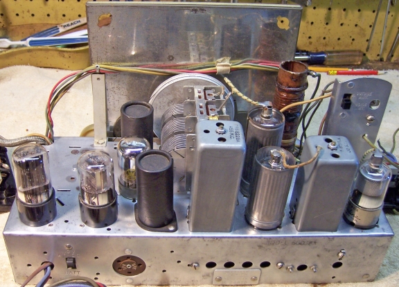
Chassis Before Restoration |
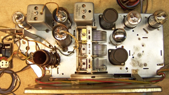
Chassis After Restoration |
 |
 |