Zenith 8S434 (8-S-434) Restoration
 |
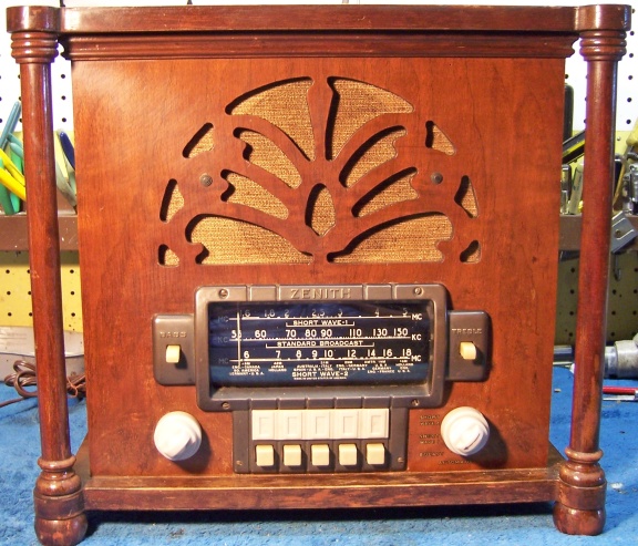
The Zenith model 8S434 (8-S-434) from 1940 is a tabletop
8-tube AC superhet circuit radio which has a unique cabinet design with
decorative turned columns.
It receives the standard broadcast band and two short wave bands, has
"automatic" or push-button tuning, and the Zenith Radiorgan
tone control (but has only two controls rather than the usual 5 or 6) The
radio had its original speaker, but the chassis had been changed out to a
5724, which is used for the model 7S434 and similar models. A
correct chassis (5810) was later found and restored. The Wavemagnet
antenna that came with the set was for the 5724 chassis, and not correct
for chassis 5810.
The schematic for the Zenith 8S434 Chassis 5810 can be found on Nostalgia
Air. Any part numbers mentioned will refer to numbers on that schematic. |
My
antique radio restoration logs
Overview
I had originally restored the chassis that came with the radio
(5724) and the radio worked, even though the speaker (49-301) was designed for
chassis 5810. The 49-301 speaker had a different field coil resistance and likely
a different output transformer than the speaker used with chassis 5724. It
always bothered me that the chassis was incorrect. I eventually found a
correct chassis on eBay. It was complete with escutcheon and tone
switches, but had no speaker. This was OK since I had the correct
speaker!
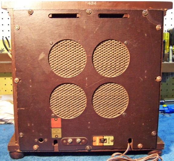
The Wavemagnet that came with the radio was likely correct for
chassis 5724, however it did not have a local/distant switch as shown on the
chassis 5724 schematic. It was also not correct for chassis 5810, since it had a single 5-pin plug. The 5810
chassis expects a 4-pin plug (only 3 used) and a two pin plug (one large and one
small pin, similar to those used in standard base tubes). But it did fit
the back of the radio correctly! I have not yet determined what radio it
came from, but it was NOT the original back on the 8S434. So my original
8S434 was essentially a Frankenradio! My strategy was to modify the Wavemagnet antenna to work with chassis 5810 (hopefully).
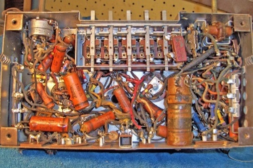
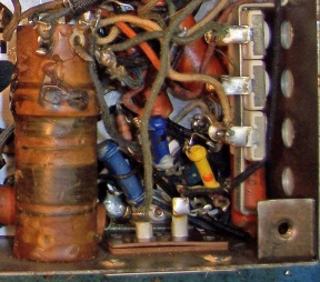
This is a very difficult radio to
service. The chassis is very compact, and the automatic tuning unit is
under the chassis. Some parts cannot be accessed without partial
disassembly. There are also errors in the Riders schematic. For
example, the schematic shows two 68 ohm wire wound resistors (R8) connected in
series between the 6K7 cathode and B+! In actual fact, these two resistors
are in parallel and connect to B-. Some of the bypass capacitors have
different values than listed in the schematic. C24 (.25mfd) was not
installed. The broadcast band padder capacitor is not pictured nor
mentioned in the alignment instructions. Here is what the chassis looked
like prior to restoration:

In Zenith schematics, all resistors and capacitors having the
same value have the same part number callout. So for example, there may be
multiple R2's or C4's on the schematic. Before I start work on the chassis
I annotate the schematic so that all parts have unique identifiers. I
usually add an alphabetic suffix, so that the part numbers are thus R1A, R1B,
etc. Once chassis photos are taken, I then annotate the photo with these
unique part numbers.
Previous Repairs
-
All the Zenith branded paper-wax capacitors were original -
none had been replaced.
-
All of the original Zenith resistors were still in place.
-
The voltage doubler input capacitor C19 had been replaced,
but the main filter capacitor C20/21/22 was original.
-
The AC line cord was cut off.
-
Most of the tubes were replacements, except for the Zenith
branded 6AF5G (unfortunately weak). The two 25Z6 and the 25AC5 tube were GT types rather than the correct G types.
Survey
My usual restoration procedure is to first make a complete
survey of the condition of all components. The survey results guide my
restoration strategy. If major and unique components are defective or
missing and
cannot be restored or replaced, I may elect to sell the radio rather than restore it.
I always assume that all paper and electrolytic capacitors are leaky and thus should be
replaced (I always "restuff" the original containers if possible).
Any mica capacitors are assumed OK until testing proves otherwise. The
automatic tuning unit (push button assembly) was removed in order to gain access
to components underneath. Fortunately, only two wires had to be
disconnected. I found:
-
The short wave antenna coil marked 2 on the schematic had been partially eaten by mice! This
was a potential showstopper! All other coils and transformers were
OK, including all the automatic tuning unit coils.
-
The Wavemagnet antenna was not the correct part for chassis 5810. It
fit the radio cabinet, and appeared identical to the antennas used on other similar
Zenith sets, but it had different connectors. Another potential showstopper.
-
Two dogbone resistors and two carbon resistors were out of tolerance.
The carbon resistors were unique in appearance but quite common in
Zeniths. They appear to have metal end caps and are not much larger
than normal 1/4 watt carbon composition resistors.
-
One of the two R7's, 22 ohms 1/2 watt wire wound, had failed - completely cracked
open! This was very likely caused by the failure of C19, the voltage
doubler input capacitor (which had been replaced). The other R7 was OK.
-
The 3-section Candohm resistor was OK. The schematic noted that the
value was 28 ohms for the filament dropping section (the two pilot lamp
shunt sections are NOT used in this chassis). The resistor itself was
marked 38/10/10 ohms, but measured about 52/14/10
ohms cold. I tested the resistor with tubes in place before starting
restoration. With 122 volts in, the tubes lit up normally, but the
voltage was slightly high (the radio is rated for 120 volts according to
Riders). The voltage to the filaments was 108 volts - should have been
101 volts. After this test, the resistor measured the specified 28
ohms hot! It was left in place pending further testing.
-
C19, the voltage doubler input capacitor, had been replaced.
The original main filter
capacitor C20/C21/C22 was still in place.
-
The two 25Z6 tubes and the 25AC5 were GT types. The 6A8G,
6K7G, 7G7(1232) and 6Q7G
were good. The 6AF5G, an original Zenith, was weak (800/1500).
-
The dial cord was broken
-
Both pilot lamps were good
Repairs
All tubes and shields were removed. The automatic tuning unit was
removed. The dial scale and pointer were removed. The tuning capacitor was
removed for cleaning and replacement of the chassis grommets. The short
wave antenna coil (item 2) had previously been removed for repair (see
below). The RF amplifier sub-chassis was eventually also removed,
since there are parts inside which have to be checked and replaced, and access
is blocked by other components.
 |
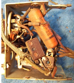 |
RF Amplifier Sub-chassis
Before Restoration |
The
chassis top and sides were then cleaned using GoJo white hand cleaner and 00
steel wool. After cleaning, the chassis was carefully vacuumed and gone
over with a small magnet and masking tape to remove any steel fragments that could later
cause problems.
I then took photos of the chassis
bottom so that routing of wiring and component placement can be restored.
Lead dress is often critical in radios. When I replace a component, I
always remove the original part completely from a terminal. Other
components connected at the terminal are protected from heat using old medical
clamps (hemostats). Excess solder is then removed using a solder sucker in order to
expose terminal holes for reattachment of the rebuilt or replaced component.
At this point, the chassis appeared as follows:

The original line cord had been cut off. It was replaced by a new brown
vinyl cord.
The dial scale that came with the chassis was not in as good a condition as
the one on the 5724 chassis (wear, one significant scratch, fading). So I swapped the
two dial scales as well as the dial pointer, installing the better ones on the
5810 chassis I intended to use with the radio (the scale was not yet installed
on the 5810 chassis pending replacement of the dial cord.)
The volume control and band switch were cleaned using GC Big Bath spray
contact cleaner/degreaser, available from Antique
Electronic Supply. The automatic tuning unit contacts were cleaned
using Caig DeOxit D5 and Q-tips, followed by a cleaning spray with Big
Bath. Contact resistance (closed) was measured prior to re-installation of
the tuning unit.
Dial Cord Replacement
The extant dial cord was broken, so a replacement was installed. This
was one of the most difficult tasks in this restoration! The tuning
shaft is hidden beneath the tuning unit compensation coil, which has four
hair-thin leads that are easy to damage. It cannot easily be removed, even
if the leads are disconnected, since access to the screw and nut that retains it
are not easily accessible. The tuning capacitor and its pulley had by this
time been installed, along with new vinyl grommets. The pulley MUST be
installed before the tuning capacitor is mounted, since it sits in a depression
in the chassis top. I did not have any of the original type dial cord in
stock, so I was forced to use a thinner type. Here is the method I used to
replace the dial cord.
- One end of the cord was first routed through the right side hole in the
chassis (view front), which is under the tuning capacitor
pulley.
- The chassis was then flipped upside down.
- The end of the cord was retrieved.
- The cord was wrapped around the tuning shaft for 2.5 turns. This was
not easy, since the automatic tuning compensation coil is in the way and
must not be damaged! I fabricated a hook out of bare buss wire which
was used to grab the end of the cord as the turns were wound - assisted by
needle nose pliers.
- The free end of the cord was then routed through the LEFT side hole in the
chassis, which is also under the tuning capacitor pulley. Before
proceeding further, you must make sure that the cord winding on the shaft is
not tangled or crossed.
- The tuning capacitor pulley was positioned so that the tuning capacitor
was at minimum capacity (maximum clockwise) and the hole in the edge of the
pulley was at about the 5:00 position.
- The end of the cord from the left side hole in the chassis was then wound
in a clockwise direction over the top of the pulley, passed through the hole in the edge of the pulley, and
attached to one end the of the original spring. The other end of the
spring was attached to the tab on the pulley designed to retain it.
- The remainder of the dial cord (projecting from the RIGHT side hole in the
chassis) was wound onto the pulley in a counter-clockwise direction, under
the pulley, and back over the top of the pulley. About an extra foot of cord was left slack, since it must pass over a small pulley on the
left side of the dial scale, over the top of the dial (retains the dial
pointer) and then onto the tuning capacitor pulley and through the hole in
the edge. I used a series of test clips as well as masking tape to
keep the dial cord in place during this process, to prevent tangling.
- The dial scale was then installed.
- The excess cord was then cut, leaving about 6" slack.
- The cord was then routed correctly and tensioned. The loose end was
routed through the hole in the pulley (along with the other end) and
attached to the same end of the spring as the other end of the cord. A
knot was then tied.
- The dial pointer was then mounted and attached to the dial cord.
- The mechanism was then tested for correct operation. Adjustments
were made to the dial pointer position and tuning capacitor pulley.
Once satisfied, I secured the knots in the dial cord using Super Glue.
The short wave antenna coil, item 2, had been partially eaten by mice!
At least they did not leave any deposits on the radio chassis. Part of the coil form as well as the topmost windings had been destroyed. At
first this looked like a fatal injury, perhaps relegating the chassis to a parts
set. The coil had three windings: a primary and two secondary windings -
one for short wave (Short Wave 2), and one for police band (Short Wave 1) Before starting repairs, or
even doing my survey, I removed the coil from
the chassis - not an easy task! It is located under the small sub-chassis
holding the 1232 RF amplifier tube and filament transformer. The
sub-chassis had to be unbolted and raised a slight amount in order to gain
clearance to remove the coil. Of course, all 5 connections to the coil had
to be unsoldered.
Once the coil was removed, it was discovered that the primary and short wave
windings were still intact! The only coil damaged was the Police band
secondary coil,
which was on the top of the form. I first melted off the wax from that portion of the coil using
a heat gun, taking care not to damage the rest of the coil. I then carefully unwound the coil, counting
turns (difficult, since about 1/3 of the coil had broken turns). The
coil was in two sections: a 4-turn section at the top, then a 0.08" gap, then a 17-turn
section below. I also measured the position of the coil sections as well as the
winding direction. I measured the size of wire used using a micrometer
(6.5 mils) and
matched it up with my stocks of magnet wire, getting as close as possible to the
original wire size used. I used 34 gauge enamel magnet wire to rewind the
coil.
The gap in the coil form was first patched using a section of a donor
coil. The patch was attached using epoxy cement after that part of the form was first
cleaned using lacquer thinner to remove any remaining wax. The coil form
was then mounted in my small Unimat lathe using an improvised jig (a screwdriver
handle). The drive belt was removed from the lathe and the belt guard
opened so that the lathe could be turned by hand. The magnet wire supply spool
was held in an improvised holder fabricated from a piece of metal strapping
screwed down to the bench, and a wooden dowel. The coil was then rewound with the correct
number of turns and spacing, keeping the winding as straight as possible (the
result was far from perfect). Once the winding was complete, it was coated
with rosin salvaged from servicing RCA Radiola Superheterodyne catacombs in
order to stabilize the winding.
Of course at this point I had no idea if the coil would work properly, and if
the Police band would properly track. There is no trimmer for the
police band.
 |
 |
 |
 |
|
T2 Damage |
Wire Removed |
Form Patched |
Coil Rewound |
Wavemagnet Antenna
The Wavemagnet antenna was modified per the schematic diagram. Only
minor changes were required. The original Wavemagnet had a single 5-pin
plug. The 5810 chassis had a 4-pin socket (no center pin) and a two pin
socket with pins similar to those used in standard base tubes (such as a 6D6) -
one pin was larger than the other. I found that the pin size and spacing
was the same as those on a standard tube base. So I salvaged the fiber
base plug of an old automobile vibrator (I never throw anything away) and cut away all except the two pins
needed and the fiber web between them. It was them cleaned up using a
Dremel Mototool sander and files. The un-needed center pin of the small
plug was removed. The wiring of the Wavemagnet was then modified to match
the 5810 chassis. Only minor changes were needed. One wire had to be
added, which shorts out the broadcast band antenna coil primary winding through
the band switch in Short Wave mode. Of course, at this
point I had no idea if this Wavemagnet antenna was electrically the same as the
one I needed. It was later determined during testing the it worked
perfectly! Here are the modified and re-created plugs for chassis 5810:

Resistors and Capacitors
All the original Zenith paper capacitors were rebuilt in their original cases
using modern 630 volt axial film capacitors in order to maintain the original
under-chassis appearance. I reseal the cardboard tubes using rosin
salvaged from servicing RCA Radiola Superheterodyne catacombs (it melts at a low temperature and will not damage
the replacement capacitors). Here
is my restuffing process for Zenith capacitors.
 |
In order to remove and restuff the capacitors on the right
side of the chassis, major surgery is required! The ground lead to
the three trimmers must be removed and the trimmer capacitors unbolted
and moved out of the way. The oscillator coil must also be
unbolted and carefully moved out of the way. Some of the bypass
capacitors are partially hidden by the band switch and one lead is
soldered to the chassis. Originally these capacitors were likely
installed BEFORE the band switch was installed! There is hardly
any room for a large enough soldering iron to replace these
capacitors. In a couple of cases, the original capacitor leads
going to chassis ground were cut, and the restuffed capacitor lead
spliced to the grounded stub. |
One original Zenith filter capacitor C19 had
been replaced. I purchased a dud twist-lock capacitor on Antique
Radio Forums Classifieds which had the correct diameter and approximate length, as well
as a black cardboard cover. It was an original Zenith capacitor, but
not the correct part number. This capacitor was opened, its contents removed, and was rebuilt using
a modern 33mfd/450 volt electrolytic cap. The dud capacitor I used had two
lugs. One was removed.
The cardboard cover for this capacitor is needed since the metal
case is connected directly to the AC line! The original main
filter capacitor C20/C21/C22 was 30/20/10mfd at
350/250/250 volts. It was rebuilt as 33/22/10mfd at 350/250/350 volts
using new modern radial lead electrolytics.
The two dogbone resistors that were out of tolerance were replaced by a NOS dogbone
resistor (that was in tolerance) and another that had drifted to near the correct value.
That one was repainted
using hobby paint to the correct color codes. While this resistor may
continue to drift, so will the others in the set. I wished to maintain the
original above and below chassis appearance. The two metal end carbon
composition resistors were also replaced using NOS and repainted dogbone type
resistors (1/4 watt) since I did not have any good original parts.
The defective R7 (22 ohms wire wound) was replaced by a 17.2 ohm 1/2 watt flexible wire-wound
resistor originally salvaged from a Philco farm radio.
Tubes
Correct G type tubes were installed except for the 25AC5G (I have not yet
found a suitable replacement). I purchased one Zenith
and one Raytheon 25Z6G on eBay. I had a good Zenith
6AF5G in stock.
Testing and Alignment
Once the radio was reassembled and the tubes installed, power was brought up
slowly using a variac. AC power consumption was monitored using a watt meter, and a
DVM monitored the B+. The radio came alive immediately and the audio
section worked. There
was some reception on the two short wave bands, but nothing on the broadcast
band. It was later discovered that I had made a wiring error, and the lead
from the broadcast band padder capacitor was swapped with another lead
originating in the RF amplifier sub-chassis. The wire colors are easily
confused due to fading and dirt. Once the wiring was corrected, the radio worked on
all bands. The automatic tuning unit was then installed, and it also
worked.
The B+ voltage was slightly low: 215 volts vs. 225 volts (at 122 volts AC
input vs. the 120 volt specification). I never figured out why this was
the case. The new filter capacitors were tested for correct capacity
before installation, and the two 25Z6G tubes were also tested (as well as
swapped). The 6AF5G and 25AC5G tubes were also substituted - no
change. The two R7 wire wound resistors were close in value to the
specifications. They were also temporarily shorted out with no B+ voltage
change noted. The wiring for the voltage doubler circuit did not match
the schematic, but I left it as it was, since it was obviously original, and
there were other errors discovered in the schematic (so I did not trust it). In any case, the
radio worked well, and the wattage draw was very close to published values in
Riders. Zenith voltages in Riders seldom match the radio in my
experience. The police band (short wave #1) also worked, so the
repairs to the mouse-eaten short wave antenna coil were obviously successful.
The set was then aligned. The radio is difficult to
align because the loop antenna and speaker must be connected while it is
aligned. One trimmer is under the chassis! There were several
problems during alignment. If the short wave band #2 antenna coil trimmer capacitor
M was
peaked for maximum output,
the radio would break into oscillation in the middle of the band. I
diddled with the wiring in the 6A8 tube area with an insulated probe - moving wires
around and changing the lead positions with respect to each other and various
components. Only minor changes in pitch of the noise resulted. So I had
to back off the adjustment of the RF trimmer M for short wave band #2 somewhat to prevent this. This likely affected
the performance on the high short wave band. The police band worked
well after the repair to the antenna coil. There is no trimmer for the
police band.
The push buttons were
adjusted to local stations. The radio performs well, and has very good tone.
Restoration Results
|
Chassis Before Restoration |
Chassis After Restoration |
 |
 |