Zenith Model 9S30 (9-S-30) Restoration
 |
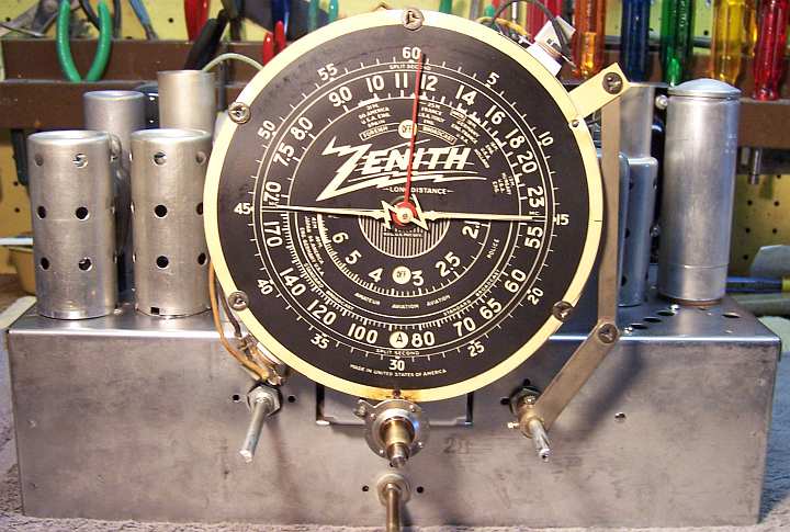
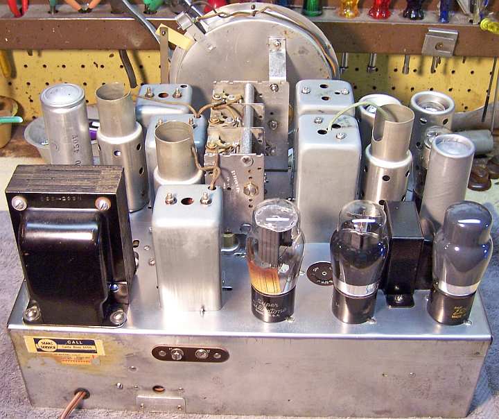
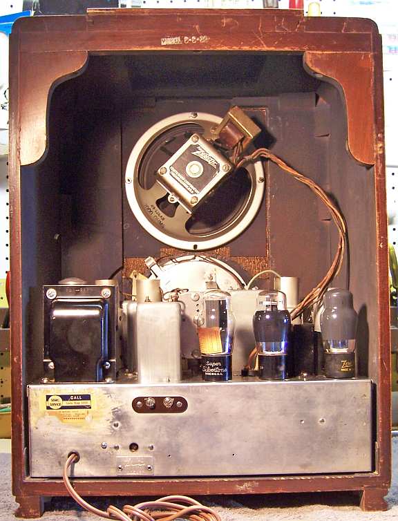
The Zenith Model 9S30 from 1936 is a large 9-tube AC superhet circuit
radio that receives the broadcast band and two short wave bands. The radio
had been serviced many times in its past, but many of the original parts
were still in place. I decided to try to reverse all prior servicing and to restore the original chassis appearance
to the extent possible. No recent restoration work had been done based on the vintage of
replacement components used.
The schematic and a parts list for the Zenith 9S30 can be found on-line on
Nostalgia
Air.
|
My
antique radio restoration logs
Overview
The radio was purchased on eBay and was sold as not working. The
seller said that it did
not power up. As found, the rectifier tube socket keyway was damaged slightly which
allowed the tube (a 5U4G was installed!) to be inserted incorrectly - which probably saved
the radio. Its
original cabinet finish was in excellent condition,. The original grille cloth was
torn. The original knobs were all present. The larger outer tuning knob was
cracked. The radio survived being shipped across the country without
damage, even though none of the chassis bolts were present! Fortunately it
was well packed and was also shipped FEDEX. There was some damage (missing wood)
to the bottom front and lower right side of the cabinet. But this damage
likely happened prior to shipment, since no missing wood parts were found in the
package.
One anomaly noted was that the
Antenna-Ground terminal strip had been installed upside down at the
Zenith factory. The rivets retaining the strip were original and
undisturbed. This meant that the labeling (A or G) was not only upside
down, but that the screw terminals functions were incorrect. The antenna
wire had to go to the G terminal and the ground to the A terminal in order for
the radio to function properly. This must have been confusing to the
original owners of the radio! I left the radio the way it was found for
historical reasons.
Previous Servicing
I always attempt to avoid purchasing radios that have been
"restored" by radio collectors or flippers, and am looking for either all
original examples or those which have been "lightly serviced" in the
distant past by radio service shops, rather than peppered with new film
capacitors. A service shop would typically replace only enough parts to restore
operation, and no more! This radio had been serviced multiple times. There were four
service tags attached to the line cord - all with different numbers (claim
numbers?). All the tags were from Art's Radio & TV Service in Santa Rosa,
CA. The telephone number on the tag was only 4-digits. On the rear chassis was a
Sears Service sticker also from Santa Rosa, CA (phone 5000). The radio was shipped by
the eBay seller from Petaluma, CA - which is in the same area of the state. All
repairs were older - no new parts (such as yellow or orange drop film capacitors)
were used. It may be possible to find some information such as the date codes
of replacement parts such as filter capacitors. Of course the replacement
parts may be much older than the repair, since they may have been in the shop's
stock for some time before use.
- Five wax/paper capacitors had been replaced.
- The volume control had been replaced.
- Electrolytic capacitors C15, C16, C17 and C20 had been replaced. C16
and C17 had been replaced by a dual 8mfd/450 volt screw based can type
capacitor with wire leads. C15 had been replaced TWICE! The
first repair was a cardboard case 30mfd/450 volt capacitor which was
soldered to the side of the chassis using one of its mounting
brackets. At some point, one section of an additional can type capacitor (screw base,
chassis mounted) marked 8-16mfd/450 volts had been connected in parallel
with the cardboard case capacitor. This capacitor had been installed
on the chassis where the original C15 likely had been mounted.
- The power cord and plug had been replaced.
- One resistor may have been replaced (R5) - or at least it was different
than all the remaining resistors.
- All the tubes likely had been replaced. There was one Zenith 6C5G
engraved base tube that may have been original - no obvious date code was found. The other 6C5G was also branded Zenith, but
had a W9R date
code (a replacement tube, likely 1939). The rectifier tube 5Y3G had been
replaced with a 5U4G (whoops!)
- No chassis bolts were present.
- The tuning shaft C-clip had been replaced with a piece of bailing wire. Normally
this clip is removed in order to install a replacement dial drive
belt. The extant (original type) belt was badly deteriorated, so it was not possible
to tell if it was original or a replacement.
- #46 pilot lamp bulbs had been installed (one was burned out). These bulbs
(250ma) are brighter and hotter than the correct bulbs (#40). This perhaps
explained the deterioration of the pilot lamp diffusers.
As parts were removed for replacement, it was discovered that some original
parts had been cut free from one of their terminals then tacked soldered
back. I assumed that a serviceman did this in order to test the part. And
when it was tested OK, it was soldered back in place.
Cleaning
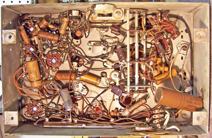
The chassis was very dusty, but not rusty. All tubes and tube
shields were removed. The dust was blown off, top and bottom, using an air
compressor. The dial, dial pan, dial drive mechanism, and tuning capacitor
were removed for cleaning and to replace the mounting grommets. The
chassis top and sides were then cleaned using GoJo (white) hand cleaner, 000
steel wool, old tooth brushes and other small brushes. The steel wool
was kept well away from tube sockets.
The tuning capacitor was cleaned using my old Heathkit
ultrasonic cleaner using dilute ammonia. This required multiple steps,
since the capacitor would not fit in the cleaner's small cleaning tank. Alter rinsing, the
capacitor was further cleaned using soap, water, and old toothbrushes. Before cleaning,
the mica trimmer insulators were removed to prevent damage. Before removal, each
trimmer was tightened and the number of 1/2 turns to tight noted. This
allowed the trimmers to be returned to their approximate original positions
after cleaning, drying, and reassembly. The ball bearings were lubricated using
Wells CL-200 automotive distributor cam lubricant (a light grease).
Survey
In Zenith schematics, all resistors and capacitors having the
same value have the same part number call out. So for example, there may
be multiple R2's or C4's on the schematic. Before I start work on the
chassis I annotate the schematic so that all parts have unique identifiers.
I usually add an alphabetic suffix, so that the part numbers are thus R1A, R1B,
etc. I then annotate the chassis photo with these unique part numbers with a red
felt-tip pen.
-
The speaker field coil was OK.
-
The output transformer was OK.
-
There were some splits in the speaker cone, and the paper
material was very brittle.
-
The driver transformer was OK.
-
The power transformer was OK. With all tubes removed, 20
volts AC was applied to the primary winding through a Variac and watt meter.
The high voltage winding was then checked for balance across the center tap.
The voltage was equal within a few tenths of a volt on each side. A transformer with shorted turns
will show a difference of more than a volt or so at 20 volts in. I
then applied full line voltage. The wattage draw was very low - less than 10
watts. All filament voltages were correct.
-
All RF and IF transformers were OK, as well as the RF chokes
and the wave trap.
-
Eight small resistors were out of tolerance by more than 20%
(some as high as 50%). All were 1/4 watt or 1/2 watt dogbone resistors. One
resistor (R5 - the 2nd detector diode load resistor) had been replaced by a newer type similar to the types used by
Philco. Its value did not match the schematic in any case.
-
R9, the five-section wire wound power resistor (Candohm) had
several sections that were not in tolerance, although none were open. Also,
I noticed that the resistance of several sections changed if a terminal was
moved.
-
The chassis bolts were missing.
-
The chassis washers were badly deteriorated and were
virtually flattened.
-
The tuning capacitor drive belt was badly deteriorated.
-
The tuning capacitor mounting grommets were deteriorated.
-
One pilot lamp socket center terminal had pulled loose from
the socket.
-
One pilot lamp was burned out, and both were #46 vs. the
correct #40.
-
One pilot lamp diffuser was in pieces and the other very
fragile due to age and heat damage.
-
The IF amplifier (6K7G) grid cap lead insulation was worn and
the conductor was shorting
to the transformer shield can.
Restoration Strategy
I assume that all paper and electrolytic capacitors are leaky and thus should be
replaced (I always "restuff" the original components if possible). I
do not replace mica capacitors, but may test them in place if possible (usually
this requires disconnecting one lead of the capacitor). Since many of the original parts were still in place I decided to try
to maintain the
original chassis appearance to the extent possible. Normally I would
rebuild all original wax-paper capacitors as well as the filter capacitors in
their original cases (restuff them). In cases where an original wax-paper
capacitor has been replaced, I attempt to find an original type capacitor in
order to restore the radio to its original appearance under chassis. I maintain
a collection of branded (Zenith, Philco, RCA/GE) as well as generic (Sprague,
CD) dud capacitor just for this situation. Fortunately, Zenith provides the part
number of the original part used. I was able to find suitable original
Zenith duds to replace all the paper capacitors that had been replaced in
servicing. All of these, as well as any remaining original parts, would be
restuffed with modern film capacitors.
All of the original filter
and other electrolytic capacitors had been removed and replaced. In one case, I
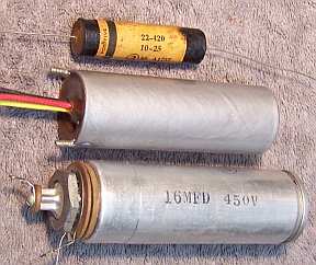
found an original dud for C20 (Zenith part 22-420, 10mfd/25 volts) in my dud
stock. But I
had no idea what the original power supply filter capacitors looked like. That triggered an
extensive investigation (as well as some chassis forensics!) See Filter
Capacitors.
I
decided to leave the (good) replacement volume control in place. It would have
been nearly impossible to find a good original control.
Repairs
When I replace a component, I always remove the original part
completely from a terminal. Other components connected at the terminal are
protected from heat using old medical clamps (hemostats). I frequently
find and remove wire stubs from previous component replacement. Excess solder is
then removed using a solder sucker in order to expose terminal holes for
reattachment of the rebuilt or replaced component.
Wax/Paper Tubular Capacitors
All original paper/wax capacitors as well as the duds used to replace
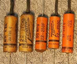
original parts removed in servicing were restuffed with new film capacitors. Here are the
(restuffed) Zenith duds. They all have the correct Zenith part number as shown on the
schematic/parts list. The two capacitors on the left are the same vintage as the
radio - the ones with the orange cases are likely vintage 1937 or later:
Four of the original capacitors used were Dubilier Cub types, which are
more difficult to restuff. Here
is the process I use to restuff these types of capacitors. For the remainder
of the original capacitors, as well as the dud replacement, here is my
restuffing process:
- The original capacitor is removed from the radio, and the required lead
length and use of insulating sleeving noted.
- The low melting point wax from each end of the original
capacitor is melted and removed using an old
25 watt soldering iron.
- The original wire leads are removed, as well as any remaining wax.
- While the internal wax is still molten, a small screwdriver is used to push out the
original paper-foil roll. In some cases, the contents come out when the leads
are pulled out.
- The original cases are then cleaned out, and any wax and dirt on the
outside removed by gently heating the capacitor tube body with a heat gun and
wiping with a paper towel while still molten.
- If the required lead length is longer than that of the replacement
capacitor, a piece of bare buss wire is attached before restuffing. The splice is
hidden inside the tube.
- The replacement capacitor is wrapped in a narrow strip of
paper towel in order to keep the new capacitor centered and to keep it from falling out.
- The finished capacitor is then sealed with melted rosin (salvaged from
early RCA Superhet catacombs, and donated by or purchased from members on Antique
Radio Forums). I do NOT recoat the outside of the rebuilt
capacitors with wax (I'm not sure what was originally used - probably
beeswax).
Filter Capacitors
All of the filter capacitors had been replaced - no original
parts remained. The Zenith schematic indicates that a single filter capacitor
was used (C15, C16, C17) rated at 16mfd, 4mfd, and 2mfd at 450 volts. My normal
process in this case would be to find duds for restuffing that looked at least
similar to the originals used. I would look for chassis photos at Radio Museum
or other sources, such as from members of Antique Radio Forums. I did in fact find
several photographs of radios that used Zenith chassis 5903 (9S30, 9S54 and
9S55) at Radio Museum:
-
9S30: This chassis used only one capacitor, apparently with
a cardboard case, mounted with studs or
L-brackets on the right (6F6) side. This chassis did NOT have a hole for an
additional capacitor on the opposite side (6A8 side) of the chassis. All of
the remaining chassis examples had the additional hole in the chassis. I felt that
this was likely the original configuration of the chassis when first
shipped. Later production chassis likely went with two separate capacitors:
C16 and C17 on the 6F6 side, and C15 on the 6A8 side.
-
9S30: Two capacitors. A round cardboard case capacitor on 6F6 side
and small non-original capacitor on the 6A8 side (this would be C15).
-
9S54: Two capacitors, one on each side. A metal can type on
6A8 side (C15). There was not enough detail to tell what the capacitor on the opposite
side looked like.
-
9S54: Only one capacitor obvious - 6F6 side. It is not clear
what type.
-
9S54: Only one capacitor - may be cardboard, 6F6 side.
-
9S55: Two capacitors. 6A8 side - metal can. Not clear what
type is used on the 6F6 side.
-
9S55: Two capacitors. 6A8 side metal can, no cardboard
cover, screw base with single positive lug and attached negative ground lug.
Insulating washers used between chassis and ground lug. 6F6 side: cardboard
case mounted with screws (it likely used threaded studs), with wire leads
(the leads had been cut flush with chassis).
I also received some information from an Antique Radio Forums
member who has restored several 9S30 chassis. One example he owns has a
cardboard case capacitor on the 6F6 side (2 x 4mfd: C16 and C17) and a metal can
type with a cardboard cover on the opposite side (C15). My 9S30 chassis
originally appears to have had two capacitors: one one each side. Based on evidence
found on my chassis, and remnants of the original wire leads, my chassis
originally had a cardboard case capacitor with two sections on the 6F6 side (C16
and C17), likely two 4mfd /450 volt units with wire leads, mounted with studs and nuts,
and a single metal can type wet capacitor on the 6A8 side (C15). The plus and
minus wiring to C15 was still in place in my chassis, although it had been cut
short when a replacement capacitor was installed. The plus lead (red) ran to the
80 rectifier pin 8. The negative lead (brown) ran to the B- lug of the
candohm resistor R9. This is the
configuration I planned on restoring if parts could be found.
For C15 (metal can) and found a Zenith 16mfd 450 volt wet
capacitor in my dud stocks (22-294 B)! This part was originally used on a Zenith
model 12A58. The capacity and voltage matched the schematic (for part C15), and
this could even be the correct type original part. It had a single positive lug
and a negative lug which is retained by the screw base mounting nut. The part
may have had a cardboard cover originally. My process for restuffing these types of capacitors is as
follows:
- The capacitor was mounted in my small Unimat lathe and I deeply scored the
case about 1" above the base (almost through the case). I
finished the cut with a fine tooth hobby razor saw then cleaned up the edges
using an Exacto knife. If the cut is done cleanly, the cut is
hardly visible after reassembly. In this case, there was
no liquid inside to be slung out as the capacitor was turned in the lathe -
it had already dried out.
- The center electrode foil and stud was removed, since the rubber
insulation on the terminal end was in bad condition and a short to the metal
case could result. The stud was replaced by a long 6-32 machine screw and
nut with solder lugs on both ends. It was insulated from the capacitor body
using an assortment of fiber washers. Before the replacement capacitor was
attached, the insulation between the positive terminal and the case was
tested at 500 volts using my Sprague TO-4 capacitor tester.
- The plus lead of the replacement capacitor (22mfd/450 volts) was attached to the
inner solder lug.
- The negative lead of the replacement capacitor was extended using solid
buss wire and insulating spaghetti tubing through a drilled hole in the base
of the capacitor near the mounting threads..
- The two halves of the case were then reattached using a PVC
plumbing coupling and epoxy. I normally am able to use 3/4" PVC
couplings to join the halves of capacitor cans together. But in this
case the capacitor can was larger than usual. I had to find a larger PVC
coupling (3/4" to 1" adaptor) at the hardware store and turn down
the diameter on my small Unimat lathe.
- Once the epoxy had hardened, the negative lead was routed through the two
fiber shoulder washers used to mount the capacitor, and attached to the
grounding lug after the capacitor was mounted on the chassis.
For C16 and C17, in my dud capacitor stock I found a cardboard case dry type capacitor with wire leads,
which mounted with threaded studs. It fit on the chassis, but was likely smaller than
the original. The case had no markings, which actually worked to my
advantage. I restuffed it with two 4.7mfd/450 volt capacitors. New wire
leads were used. The cardboard case was painted using silver/aluminum enamel.
For C20 (10mfd/25 volts) I found an original dud in my stocks (Zenith part
number 22-420). It was restuffed using a 22mfd/50 volt capacitor. It was quite
difficult to clean out the old contents since it was sealed with tar. The
original label was damaged when it slipped off of the tube during the
process.
Metal Clad Power Resistor (Candohm)
Several sections of the metal clad power resistor R9 (Muter
Candohm type) were out of tolerance. Also, the resistance of a few
sections varied when the terminal lugs were moved. However no sections
were open, and the insulation appeared to be in good condition. These resistors
are constructed using clamps (holding the terminal lugs) around the resistance
element. The clamps/terminals are not fastened to the resistance strip.
Over time, the insulator on which the resistance wire is wound shrinks, or the
clamps expand. This results in a high and unstable resistance, or even an
open section in extreme cases. I have found that if pressure is applied near
each terminal lug, often the resistor can be repaired. My preferred method is to
remove the resistor from the radio (usually attached using rivets) and exert
pressure on both sides of the case using my large bench vice. Alternately,
C-clamps can be used. This is the method I used in this case, since I did not
want to disturb the wiring or risk damage when drilling out the rivets.
This "repair" method only has a chance of working if
the fish paper insulation is in good shape, with no signs of heat damage or
deterioration. If this insulation fails, the result is usually a B+ short to the
metal case (which is grounded). This could destroy the power transformer or
other parts. Most collectors routinely remove the Candohm and replace it with
several wire wound resistors mounted on terminal strips, even if the resistor is
good! While
this is the most reliable method of repair, it does destroy all originality
under the chassis. It is also difficult to find replacement wire wound
resistors with the correct resistance and wattage. Often several resistors in
series or parallel must be used for each section.
After applying clamps at each terminal location (only one
side of the resistor was accessible), all sections were in tolerance (some
exactly) and all resistances were stable when the terminal lugs were moved.
Small Resistors
Nine small resistors were out of tolerance by more than 20%
(some as high as 50%). All were 1/4 watt dogbone resistors. One
original resistor R5 previously had been replaced by what looked like a
Philco type carbon resistor. The schematic called for a 650K
resistor. A 470K was installed. It is unusual that this particular
resistor would be replaced, since it is in a difficult position to access, and
is in parallel with a mica capacitor. I collect NOS as well as used dogbone
resistors just for this purpose, and buy all I can find on eBay and at swap
meets. In most cases I did not have replacements available that were in tolerance.
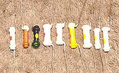
In these cases I attempted to find a replacement that was the correct size and
had the correct measured value (within 20% tolerance) but not the correct
markings! I then repaint the resistor with the value required using hobby
enamel paint. In the photo below are the repainted resistors:
Tubes
Some of the original tubes were re-used if good or only slightly
weak. The 5U4G was replaced with a 5Y3G. Correct G type tubes were installed for
the 6A8 and 6H6GT. The two 6F6G tubes were good, but very different in quality.
One measured 1500 and the other measured 2200 (target was 2000). I also noticed
that the hum balancing control was all the way to one side. So I substituted two
more closely matched 6F6G tubes.
Pilot Lamp Socket
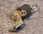
The center terminal lug of one of the pilot lamp sockets had
pulled loose due to failure of the rivet. The socket was disassembled by
removing the remnants of the rivet, the internal and two external fiber shoulder washers,
and the copper center contact spring. Unfortunately the inner fiber insulator
was damaged and could not be reused. A replacement was fabricated using a #6
fiber washer that was sanded down to fit inside the screw base of the socket.
The rivet was replaced using a 6-32 brass screw and nut. The head of the
brass screw was ground down flat and to size so that it could be used to retain
the copper inner contact spring. The socket was then reassembled and the
original terminal lug reattached using a 6-32 nut.
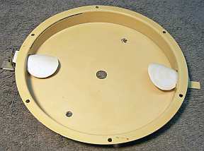
Pilot Lamp Diffusers
Zenith as well as other manufacturers used pilot lamp diffusers
to protect the plastic dial from the heat of the pilot lamps. It is very common
to see Zenith black dials with holes burned in them. In many cases, the 150ma
pilot lamp is replaced by a larger wattage 250ma bulb. In my case, one
diffuser was in pieces. The other was intact but very fragile due to age and
heat. It was broken during removal. Removal required gentle heating with a heat gun.
Once removed and somewhat flattened, a rough template was traced onto a piece of
thin cardboard (the back of a writing tablet) The tracing was difficult
since the original part was in several pieces. The cardboard pattern was then
refined and cut out using an Exacto knife fitted with a new #11 blade. This pattern was then
used to cut two replacement diffusers from a suitable piece of white plastic
sheet. If I recall, the plastic was originally cut from a food carton.
Other Repairs
- The line cord was replaced with brown vinyl "zip" cord with a
molded plug. The original would have been brown rubber with a round molded plug.
- The badly deteriorated chassis washers were dug out of the cabinet
recesses and replaced by part CW-1 (1 1/4 x 3/8 thick) chassis washers from Renovated
Radios.
- I was able to obtain a set of four original Zenith chassis bolts on eBay.
They were originally from a Zenith chassis 1004, a similar deep chassis
radio. I am almost certain that these were the same as what was
originally used in my radio.
- The tuning capacitor mounting grommets were replaced using part G35Z-Tuner
(set of three) from Renovated
Radios.
- The tuning drive belt was replaced using belt 128 from Adams
Manufacturing.
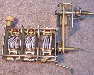
- The dial drive gearing and reduction drive assembly were removed from the
tuning capacitor and disassembled. The parts were then cleaned using lacquer
thinner followed by cleaning using an ultrasonic cleaner and dilute ammonia
followed by rinsing and drying. The reduction drive assembly was lubricated
prior to reassembly using Wells CL-200 automotive distributor cam lubricant.
- The IF amplifier tube grid cap lead had deteriorated was shorting to the
transformer shield can. To replace the lead, the grid cap was first removed.
Then the transformer shield can was removed, leaving the IF transformer
assembly still connected. A new lead was attached (green cloth covered wire)
and routed through the transformer shield. The shield was then reinstalled
on the chassis and the grid cap replaced.
 |
Cleaned, Lubed and Rebuilt Tuner Mech
|
Cabinet
The cabinet was vacuumed then cleaned using GoJo (white) hand cleaner and 000
steel wool. Nothing else was done to it. The torn grille cloth was left in
place, since it was original.
Testing and Alignment
After completion of the electronic restoration, power was applied through a
fused Variac and watt meter. A DVM monitored the B+ voltage. Power
was slowly increased while B+ and wattage draw was monitored. The radio came
alive and worked on all bands. The only glitches were the tone control
(scratchy) and an intermittent tube socket (6C5 first audio amplifier). The tone
control was given a shot of GC Big Bath cleaner, after which it worked OK. Pin 5
of the 6C5 first audio amplifier tube socket was not making a firm connection,
resulting in intermittent operation, hum, and static. The tube was pulled and
the socket contacts gently squeezed using needle nose pliers. After that,
operation was OK. The radio worked on all bands.
The speaker had a noticeable rattle at even low volume, and especially if the
tone control was set to boost the bass response. There were several bad splits,
and the cone material was very brittle. The splits were repaired with several
coats of GC Service Cement. After that, most of the rattle was gone.
The radio was then aligned. The instructions given in Riders (Nostalgia Air)
are very brief, hard to read, and are incomplete. I received some help from the
good folks at Antique Radio Forums
and was able to complete the alignment process.
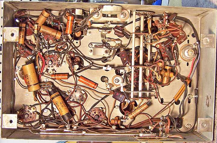
Restoration Results
My original restoration objective was to return the radio to its un-serviced
condition - to reverse any prior servicing - and to restore operation. Ideally no
repairs would be visible. Not all restoration objectives were met, as some of
the original replacement parts were not available or were unknown. Some of
my "misses" were:
- Three of the Zenith dud paper capacitors used to replace originals removed
in servicing were later (1937) vintage. While they had the correct
Zenith part numbers and values, they were a different color and appearance
vs. the original parts.
- The volume control had been replaced.
- The power cord was similar to the original type, but not the same.
- One of the replacement filter capacitors was not like the original.
In fact, I was not able to find a photo of an original capacitor (C16-C17).
The replacement C15 was an original Zenith part with the correct value and
voltage rating. However it was from a different Zenith model (but the
same year) and did not have an insulating cardboard cover (as the original
likely would have had).
|
|
 |
Chassis After Restoration
|
 |
