RCA Model 100 (Late) Cathedral Restoration
My
antique radio restoration logs
|
|
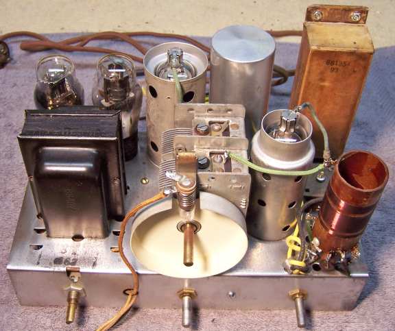
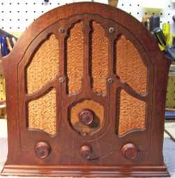
The RCA Model 100 (Late Version) from 1933 is a 4-tube AC non-AVC superhet circuit
radio. It receives the standard broadcast band and the old police
call band. The only schematic I have been able to find for this
radio is at Radio
Museum. Membership is required for access. The Riders Manuals
and Nostalgia Air include the early version schematic listed under
RCA
101 and information on a chassis similar to the Late Version under
the RCA
301. All parts references
are to the Radio Museum schematic (most of which apply to the Early
Version in Riders). |
Overview and Prior Servicing
The radio was purchased on eBay. It was said to power up and receive
static but no stations. I slowly powered up the radio using a
fused variac and watt meter in order to verify the eBay seller's claim. It did
indeed power up OK and there was some noise from the speaker. I normally never
apply power to a radio until it is first restored. But in this case it was
known that the seller did apply power (likely full line voltage).
I always attempt to avoid purchasing radios that have been
"restored" by collectors or flippers, and am looking for either all-original examples or those which have been "lightly serviced" in the
distant past by radio service shops, rather than peppered with new film
capacitors. Service shops would typically only replace the minimum number of
parts. Based on the eBay photos provided, all of the top chassis parts were still in place and there were no signs of any
restoration or repairs. The line cord was original and the cardboard cased
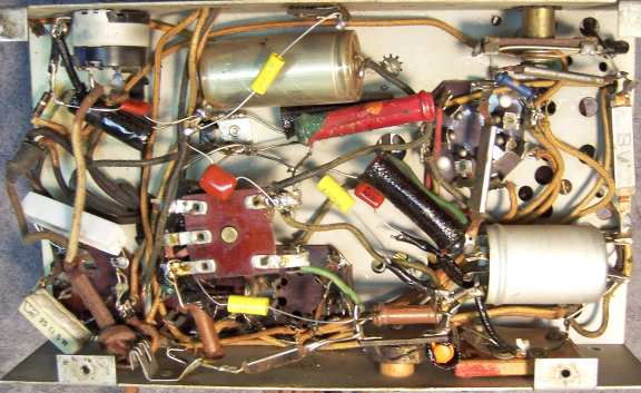
filter capacitor was still in place. But when I pulled the chassis, I was disappointed to say the
least! All except one wax/paper capacitor had been replaced with modern film
capacitors.
And one of the original capacitors had been replaced by a
disc ceramic. A tubular filter capacitor had been tacked in under the chassis, although the
original filter capacitor was still connected. All the original
resistors were in place. The volume control and pilot lamp socket had been replaced.
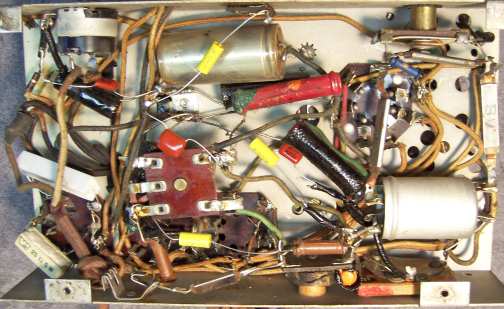
On thing was very worrying: there were a couple of power resistors (5 and 10
watt) plus some diodes found connected to the 1-V rectifier socket. I was very
concerned that the power transformer had failed and that this was some sort of
work-around. But after analyzing the circuit as wired, it was discovered that
the added components and modifications were simply a replacement for a burned
out 1-V rectifier tube! This was a lot of work to replace a very common
tube. Whoever did this substituted a 25 ohm 5 watt resistor for the tube's
filament, and a 120 watt 10 watt resistor in series with two diodes (in parallel!) for the
rectifier function. This radio's circuit is quite unusual in that the 6A7, 6F7,
and 1-V tube filaments (all 300ma) are in series and connected between a 6 volt and 24 volt
tap on the power transformer's single secondary winding. The 6 volt tap
supplies power to the 41 output tube filament and the pilot lamp. So all I had to
do to reverse this "repair" is to remove the added components and plug
in a good 1-V tube.
I decided to try to reverse any previous servicing to the extent possible
and to restore as much of the original chassis appearance as possible. My objective was that any repairs or
restoration would not be obvious, and no new parts visible. All of the missing
original capacitors and replacement volume control and pilot lamp socket would limit success in
restoring originality. Even if original capacitors could be found, their exact
locations in the chassis was unknown since all but one had been replaced. The
provided RCA connection diagram is helpful, in that at least connecting points
are documented. But the only such diagram is for the early version radio, and
there are differences. It is not known if the schematic and connection
diagram for the RCA
301 Duo (in Nostalgia Air, ignoring the phonograph connections) is the same
as the RCA 100 Late Version.
This same or similar chassis is used in other RCA and GE radios. The Riders
manuals contain the early version schematic, parts list and connection diagram.
That information is available
on-line at Nostalgia Air under the RCA
101. Radio Museum has both the early and late version
schematics. The main difference between the early and late version is that the
early version uses a type 38 output tube. The late version uses a type 41
output tube. In the early version, since all tubes are 300ma, they are all in
series and connected to a 24 volt tap on the power transformer high voltage
secondary. The 6 volt tap is only used for the pilot lamp. In the late
version, the 41 output tube (400ma filament) and pilot lamp share the 6 volt tap.
The three remaining 6 volt tubes are in series and connected between the 24 volt
and 6 volt taps. One other difference I noticed is that the tone capacitor C20
is 0.025mfd for the early version and 0.017mfd for the late version. The output
transformer is also likely different due to the different audio output tubes
used (different DC resistances on the schematics). This radio uses half wave rectification for the B+. The power transformer
has only a single secondary winding with multiple taps.
Survey
My usual restoration procedure is to first make a complete
survey of the condition of all components. The survey results guide my
restoration strategy. If major and unique components are defective and
cannot be restored, I may elect to sell the radio for parts rather than restore it.
I assume that all original paper and electrolytic capacitors are leaky and thus should be
replaced (I always "restuff" the original containers if possible).
In this case, most of the original paper capacitors had been replaced.
Since this radio actually powered up and made some noise, it was assumed that all major parts were OK.
-
The volume control (4K with switch according to the
schematic) had been replaced. The replacement measured about 5.6K
ohms. At this point I did not know if the replacement control had the
correct taper. A couple of carbon resistors in series provided a minimum
resistance which was likely built into the original control but not the
replacement.
-
The 1-V tube had an open filament. The 6F7 showed a
short. The other two tubes were OK.
-
Three resistors were out of tolerance. All were old style
"dogbone" resistors in various sizes.
-
The speaker field coil, cone, and output transformer were
OK.
-
The power transformer was OK.
-
The IF transformers and all RF coils were OK.
-
Both RF chokes were OK.
-
The original power cord had several questionable areas, and
the plug was broken and had been taped together.
Repairs
First, all non-original parts were removed after taking careful notes of where they
were connected.
Paper Capacitors
Only one original paper-wax capacitor remained: C1, 0.01mfd. But this
told me what the remaining (now missing) capacitors should look like.
Early RCA/GE paper capacitors of this era were simple cardboard tubes with each
end sealed with tar. No value or voltage rating appears on the part - only
a 5 digit number such as 69031 (sometimes there is a suffix also). This number bears no apparent relationship to the
RCA part numbers listed in the parts list. I maintain a collection of dud
capacitors just for this situation. My collection includes branded (Zenith,
Philco, RCA/GE) as well as generic (Sprague, CD, etc.) parts. I had
previously restored an RCA 301 which has a similar chassis. In my
restoration notes for that radio, I had noted the part number for each of its
capacitors (which were restuffed). This gave me the part numbers for most
(but no all) dud capacitors to look for in my collection. I had
appropriate sized RCA/GE duds to replace the capacitors that had been removed,
but only had the exact part in one case.
The one original and all replacement paper capacitors were rebuilt
using modern 630 volt axial film capacitors in order to restore the likely original
under-chassis appearance. These types of capacitors are very easy to
restuff. First the component leads are pulled out of each end, which also takes much
of the tar with them. Then the foil roll is pushed out one end using a
screwdriver. The cardboard tube is then cleaned of any remaining tar. I also clean the outside of the tube by heating with a heat gun and
wiping away the wax, tar, and dirt. A new axial film capacitor is then
inserted. Before restuffing, the
component's original lead length and any insulating sleeving use is noted. In
some cases longer leads must be first attached to the replacement capacitor
before restuffing (I use #20 or #22 solid tinned buss wire to extend the leads).
Here is the method I use
to rebuild cardboard tube type capacitors.
One capacitor C20/C21 was a dual capacitor (0.017mfd and 0.005mfd), with wire leads. One of the existing leads from the output tube
plate was still in place. I chose a suitable sized RCA/GE cardboard tube from my dud
stock, which was restuffed using .015mfd and .0047mfd 630 volt film
capacitors.
Capacitor C15 (2400pf) had been replaced using a 2200pf disc ceramic capacitor. It is unknown
what type of capacitor was originally used. It could have been a metal clad mica
type, since there are quite a few of this type used in the radio, and the early
version connection diagram hints of this type. I also
have chassis photos of an RCA 301 Duo and a GE M-49 both of which use an almost identical
chassis. One such chassis used a normal flat brown bakelite mica capacitor with flat leads
terminated in a ring. Another radio used an RCA/GE tubular capacitor
sealed with tar, like all the other paper capacitors in my radio. Since
the capacitor had been REPLACED, and since no other mica capacitors were replaced,
then I
had to assume that the original must have been a tubular. In yet another RCA/GE
restoration, in the process of restuffing this very same capacitor, I discovered
that inside was a metal clad MICA capacitor rather than the usual foil/paper
roll! It was tested and good, so I simply resealed the tube.
Two capacitors, C10 and C18 remain a mystery at this writing. The values,
types and placement used vary depending on the model. And I have never seen an
actual original example of C10 as a 4mfd tubular.
- In the RCA 100 and 101 (Early Version) and GE M-41, C10 is specified as
0.25mfd for 60Hz and 4mfd for 25Hz models. In the RCA 100 (Late Version),
RCA 103, RCA 301 Duo and GE M-49, C10 is 4mfd. In my radio as received,
one section of the original filter capacitor (blue wire, C23 8mfd) had been moved and
used for C10 and a 20mfd/450 volt capacitor had been tacked in to replace
C23.
- In the RCA 100 and 101 (Early Version) and GE M-41, C18 is specified as
0.1mfd. In the RCA 100 (Late Version), RCA 103, RCA 301 Duo and GE M-49, C18
is 0.25mfd. In my radio as received, a 0.05mfd capacitor had been installed
to replace it.
- The early version connection diagram shows that the C18 (0.1mfd) ground
lead is soldered to the rear chassis. The RCA 301 and GE M-49 show that C18
(0.25mfd) is connected to a single terminal strip on the rear chassis with a
wire running to the junction of R8 and R9 on the detector plate choke - the
other end is connected to a 4-way chassis ground lug.
My example radio showed no trace of either solder or of a terminal strip on
the rear chassis. But there was a hole in the chassis where a terminal strip
could have been mounted.
I decided to replicate the configuration used by the RCA 301 and GE
M-49. I installed a single lug terminal strip similar to the original seen
on an RCA 301 on
the rear chassis and used a restuffed 0.25mfd capacitor for C18. I had an
original part to restuff in this case - which looked like a block of tar wrapped
in thin paper. Here is how I restuff
this type of capacitor. For
C10 I used an RCA/GE dud paper capacitor which was the appropriate size and
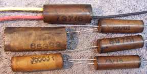
restuffed it using a 4.7mfd/450 volt axial electrolytic capacitor. Here are the
restuffed capacitors:
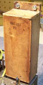
Filter Capacitor Block
The original cardboard cased filter capacitor C22/C23 (2 x 8mfd high voltage)
and C13/C19 (2 x 5mfd low voltage) was opened up and
restuffed using two 10mfd/450 volt and two 4.7mfd/450
volt electrolytic capacitors. The rivets holding the capacitor box to the
upright metal mounting bracket were first drilled out. Then the
backs of the hollow eyelets holding the cardboard box together were ground off using a Dremel Mototool with a
grinding stone. The eyelets could then be removed from the top with minimum
damage to the cardboard case, and could be reattached later. The stiff bottom cardboard
base was then removed using a
heat gun to melt the glue and wax. The capacitor case was then carefully
opened, again using the heat gun. The capacitor inside as well as the
original wire leads were then removed
after severing the foil connections to two internal terminal rivets. Two 4.7mfd at 450 volt capacitors
and two 10mfd at 450 volt capacitors were
then mounted inside. All of the original wire leads were re-used. The two
5mfd (4.7mfd) and two 8mfd (10mfd) capacitors have separate common negative
leads.
The capacitor was then reassembled and held together
using hot glue. The bottom cardboard base was reattached using hot
glue. The two eyelets were then reinstalled. They are held in place
by the capacitor's mounting screws.
Resistors
Three original resistors significantly more than 20% out of tolerance were replaced. I
used dogbone type resistors as were used originally. I purchase all the
reasonably priced NOS
and used dogbone resistors that I can find on eBay or at antique radio swap
meets. I picked out NOS and used
dogbone resistors from my collection that were either in tolerance or had drifted to the correct needed resistance and then repainted them to
match the original resistor's color codes using hobby enamel paint. Another
consideration is lead length. The replacement resistor's leads would ideally be
long enough to reach each connection point without having to splice the lead.
- R4 (25K 3 watt) was replaced using a 27K 10% 3 watt dogbone resistor that
measured almost exactly 25K. It was repainted as 25K (20%) using hobby
enamel paint.
- R8 (170K 1/2 watt) was replaced by a 150K 1/2 watt dogbone that measured
161.8K.
Only the end color needed repainting (violet vs. green).
- R11 (500 ohm 1 watt) was replaced by a 400 ohm 1 watt dogbone that
measured 530 ohms. It
was repainted as 500 ohms.
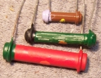 |
Here are the replacement dog-bone
resistors, ready for installation in the radio.
|
Volume Control
The volume control had been replaced. The replacement was likely a 5K
potentiometer with switch (it measured 5.6K). The original was 4K according to the schematic.
My IRC Volume Control Replacement manual called for an IRC type D11-113 which is 4K
ohms with an A taper (linear) and no series resistor (minimum resistance).
Whoever installed the replacement control added a 680 and 100 ohm resistor in
series. So perhaps the original control had a minimum resistance of 750
ohms or so. My plan was to try the existing control (5K) without the series
resistance.
My concern was that the taper of the replacement control was correct. In this
application, a potentiometer with a linear or normal volume control type taper
may not work well in spite of the IRC recommendation. The original part was likely a reverse taper part. If the
incorrect taper is used, all of the control of volume will be crammed into the
last 25% of shaft rotation. I attempted to measure the taper by attaching a
chicken-head pointer knob and mark points on the chassis at 0, 25%, 50%, 75% and
100% rotation. I then measured the resistance at each of those points in order
to plot the taper. Rough measurements were:
Knob Position Linear Installed
Replacement Control Resistance
0
5670 5670
25%
4252 3820
50%
2835 1970
75%
1417 443
100%
0 0
So it appears that the installed (replacement control) has some sort of
reverse taper, which is needed in this application. Only testing will tell
if it works OK!
Other Repairs
- The chassis was cleaned using GoJo and steel wool, tooth brushes, small
bottle brushes, and pipe cleaners. Since use of steel wool may leave
behind conductive fibers, I then went over the chassis with small magnets, a
vacuum cleaner, and masking tape.
- The band switch was cleaned using lacquer thinner.
- The original line cord was re-used. About 12" was removed from
the end, as there were multiple damaged areas. A damaged area near the
chassis was repaired using small pieces of electrical tape and shrink
tubing. This allowed me to retain the original under-chassis power cord
connections and strain relief knot. The broken power plug was replaced using
a similar bakelite acorn style plug. It is not known if the broken plug was
original.
- The existing (and original) antenna and ground leads were very
short. They were replaced with new cloth covered wires rather than
splicing on new wire.
- The 6F7 grid cap lead was replaced. The original was rubber covered
and the insulation was falling off. It was replaced using new green cloth
covered wire. This required removing the second IF transformer shield in
order to access the connection point. Routing the lead underneath the
transformer base then up through the base to the transformer terminals is
quite tricky, and will require some patience.
- The detector plate choke (L8) was good when first checked. But during the
process of replacing resistors R8 and R9 (attached to the coil) I must have
damaged the coil, or it may have decided to fail. I had to remove the choke
from the radio and attempt to repair it. Using a sharp Exacto knife (with
#11 blade) as a probe, I determined that the break was about 2/3 the way up
from the base of the coil. So I started unwinding the wire from the
top until a break was found. The broken end was then connected as the start
of the winding. The original resistance was 87.7 ohms (spec was 100
ohms) - after repairs, it was 51.9 ohms. I assumed that the choke would still work
satisfactorily.
- The pilot lamp socket had been replaced, but the installed socket pointed
the lamp sideways vs. downward and inside the dial cover housing. As
found, the dial scale was not properly illuminated. The
socket was replaced by a more suitable socket that pointed the lamp in the
correct direction. It also accepted a screw based bulb like the one
used in the RCA 301. The only problem was that it had two lugs vs.
one, and a ground had to be arranged. The existing lamp wire (which
had been spliced to the installed socket) would reach to the lugs on the
replacement socket without a splice.
Testing and Alignment
Once the radio was reassembled and tubes installed, power was brought up
slowly using a variac. AC power was monitored using a watt meter, and a
DVM monitored the B+. The radio came alive immediately and worked. The set was
then aligned. The oscillator could not be set to scale. With the oscillator
trimmer completely loose, the dial frequency was about 50kHz too high, and the
tuning knob could not be moved on the tuning capacitor shaft to compensate due
to the flat portion of the shaft. The dial pointer (plastic) was attached to the
back of the knob and also could not be moved. I assumed that this frequency
error was due to changes
in the oscillator coil due to age and perhaps absorption of moisture. The radio picked up lots of stations
using my basement ceiling mounted 30' antenna. It even picked up some stations on the "police"
(low short wave) band
in the middle of the day.
The volume control provided a good adjustment range near maximum volume, so
the taper of the replacement control was acceptable but not ideal. If the volume
was set close to maximum (with no station being tuned) the set would break into
oscillation. I assumed this meant that the original volume control likely had a
minimum resistance. And in fact, the previous "restorer" had
installed 680 and 100 ohm resistors in series with the control. When I checked
for oscillation at various points on the dial, I found that about 400 ohms was
needed as a minimum resistance. I installed a 390 ohm 1/2 watt resistor in
series, hidden inside black spaghetti tubing.
Restoration Results
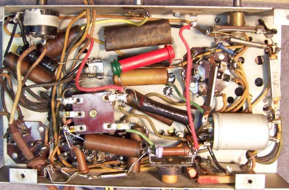
I was not able to successfully reverse all previous repairs and to restore the radio
to its un-serviced appearance. No replacement parts are visible except for the
volume control, grid cap leads, and some wiring including the antenna and ground
leads. It is likely that some of the components were not in exactly the
same position as installed at the factory, since the radio had already been
"restored" (recapped) when I received it. I did not have an
unrestored under-chassis photo to refer to - only some photos of RCA/GE radios
with similar chassis. The paper capacitors which were restuffed were not the
correct RCA part numbers as used originally. Only one original paper capacitor
was intact - the remainder were from my dud capacitor stock.
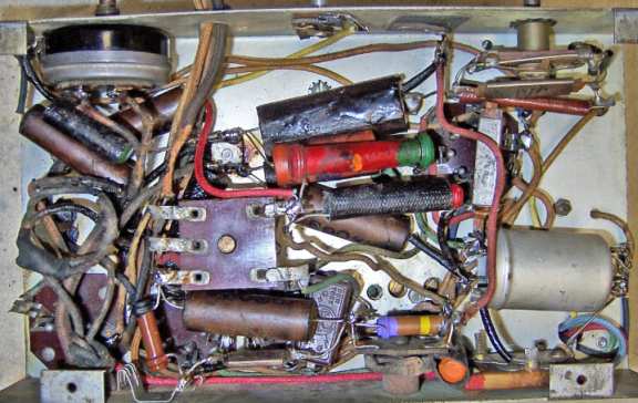
Chassis Before Restoration
|
 |
Chassis After Restoration
|
|
Similar RCA 301 Chassis For Reference
|
 |
