US Radio & Television Model 24 Restoration
|
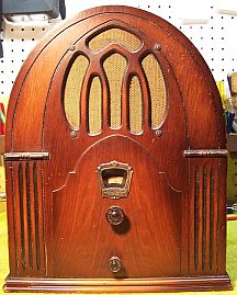
The U.S. Radio & Television Model 24 is an 4-tube AC superhet circuit
radio in a small cathedral cabinet. As purchased, the radio was
stated as powering up with weak reception. It receives only the broadcast band.
The radio had been serviced in the distant past, as well as some recent restoration judging from the age of the parts used.
I decided to
attempt to reverse
all previous repairs to the extent possible and restore the original above and below chassis appearance. The schematic for this radio can be found on-line at
Nostalgia
Air. |
My
antique radio restoration logs
Condition As Found
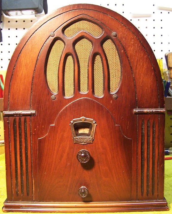
This radio was purchased on eBay. The cabinet was in
good original condition, as were the
knobs and grille cloth - just the usual wear, dings and scratches. The
radio was sold as powering up with weak reception. The only evidence of
prior restoration visible in the eBay listing was the antenna and ground leads, which had been
replaced by modern plastic covered wiring. The line cord
and plug were original,
and in good shape. I always avoid knowingly purchasing a radio that has been
restored, as many collectors take shortcuts such as removing the original capacitors and filters. Since
the seller did not mention hum, it was likely that at least the filters had been
replaced. There was no sign of an original above chassis filter capacitor
having been removed.
Circuit
The Model 24 is a 4-tube superhet circuit radio that receives
the broadcast band only - typical in 1931/32. The circuit is quite
unusual. It consists of a standard first detector and oscillator tube
followed by a regenerative detector! There is no IF amplifier stage and
only one IF transformer. The regeneration is not user adjustable - it is
set during alignment, and would greatly increase the gain of the detector
stage. Of course, if the regeneration setting is advanced too far, the set
would break into oscillation. The Model 24 is a non-AVC set, which means that the volume control must be
manipulated while tuning to prevent blasting, overloading, or completely missing
weak stations.
Previous Repairs
The radio had been serviced perhaps several times. This
was a "well loved" radio, and someone had paid a lot of money to keep
it running! A few newer components indicated that more recent repairs had
also been done, perhaps by a collector.
-
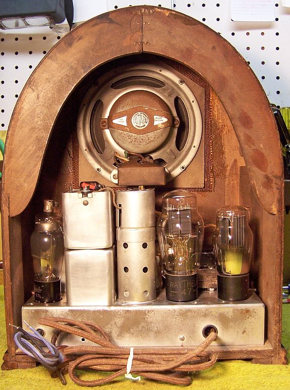
Three of the four tubes (two 57's and 80) were National
Union brand with date codes of H or L. These tube are likely the originals. The 47 tube was a Raytheon and likely a replacement.
There is no way to know for sure what brand of tube was originally
installed, but usually all tubes are the same brand.
-
Only one original wax/paper capacitor remained. Two
capacitors had been replaced (C-8 and C-11): one with an older vintage capacitor and one with a modern
film capacitor. The remaining original capacitor was a Dubilier CUB
type, which is typical of early 30's radios. It is likely that the
other capacitors originally were the same type.
-
The original filter capacitor had been removed and replaced
by three modern tubular electrolytics. The original filter capacitor was likely a
rectangular cardboard case affair consisting of two 8mfd filters and a 4mfd
low voltage filter. There were empty screw holes in the chassis which indicated the
original position of the capacitor under the chassis, as well as its
mounting centers. Wiring location clues also indicated where the
original terminals were located, and part of an original solder lug still
remained.
-
Two resistors had been replaced with older 1 watt carbon
composition type resistors (R-5 and R-7). All the remaining
resistors were old-style "dogbone" types (two were cast-end
types).
-
The volume control and switch had been replaced. The
original was 20K ohms, and likely had a reverse taper since it shunted the
antenna coil primary (rapid resistance change from minimum volume position -
exactly opposite of a standard volume control). It had been replaced
by a 10K linear taper type control. The IRC reference manual
indicates that the correct replacement control is a D16-119 20K with dual taper. I
just happened to have one in stock if needed.
Survey
My usual restoration procedure is to first make a complete
survey of the condition of all components. The survey results guide my
restoration strategy. If major and unique components are defective or
missing and
cannot be restored or replaced, I may elect to sell the radio for parts rather than restore it.
I always assume that all paper and electrolytic capacitors are leaky and thus should be
replaced (I always "restuff" the original containers if possible).
Any mica capacitors are assumed OK until testing proves otherwise.
-
The speaker field coil was OK.
-
The output transformer was OK.
-
The power transformer was OK. With 20 volts applied to the
primary through a variac, the high voltage was balanced across the center
tap which indicated that there are no shorted turns (a common failure
mode). The the wattage draw at full line voltage was less than 10
watts (real analog watt meter, tubes removed).
-
All tubes were good. The grid cap on one of the 57 tubes was loose and not properly repaired
(the lead was soldered but the cap was not cemented to the top of the tube).
-
The power cord and plug were original. I planned on attempting to re-use it.
-
Two original dogbone resistors were out of tolerance (R-3 and R-4). One was
1/4 watt size, one was 1 watt. Two resistors had been replaced, and were likely
originally 1/4 watt dogbone type resistors.
-
Almost all wiring in the radio was cloth covered and was OK. The
antenna and ground leads had been replaced with modern plastic wire.
-
The antenna and oscillator coils were OK.
-
The IF transformer was OK.
-
The tube shield was present.
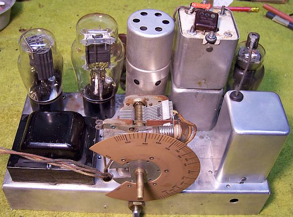
Repairs
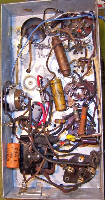
Before starting repairs I made BEFORE photos of the chassis bottom. I use these photos to ensure that replacement parts and
wiring are placed as close as possible to their original positions. Some
radios are subject to problems such as oscillation or motor boating if wiring is re-routed or
lead dress is not the same as the original. Since this radio had been
heavily serviced or restored, I could not count on any of the wiring or
component placement being original.
All tubes and the tube shield were removed. The tuning capacitor and dial
assembly was removed for cleaning.
The top and sides of the chassis were cleaned using GoJo hand cleaner and 00
steel wool. Since this may leave behind metal fragments, I follow up this
cleaning with a good vacuuming, a small magnet and masking tape. The
tuning capacitor was cleaned in my old Heathkit ultrasonic clean using dilute
ammonia. After drying with a heat gun, the bearings were lubricated using
automotive distributor cam lubricant, which is similar to the original grease
used.
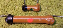
Resistors
Two original dogbone resistors were out of tolerance by more than 20% and two
others had been replaced with older type 1 watt carbon composition type resistors. Three
original resistors were likely 1/4
watt size and one was definitely 1 watt. I collect NOS as well as used dogbone
resistors, and buy all I can find on eBay and at swap meets, at reasonable
prices. I did find one 500K 1/4 watt dogbone that was in tolerance, but
not the other three needed. In these cases I attempt to find a replacement that is the correct
size and has the correct measured value (within 20% tolerance) but not the
correct markings! I then repaint the resistor with the value required
using hobby enamel paint. In this case I did find suitable
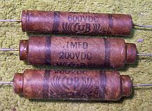
replacements. Examples below - the 1 meg resistor was originally 820K, now
measures 1.1 meg.
Bypass and Coupling Capacitors
Only one original paper tubular capacitor was still in place. It was restuffed using
a 0.1mfd 630 volt film capacitor. It was a Dubilier Cub type, which are difficult to restuff since they have a wooden
dowel down the center! Here is
my method of restuffing Dubilier Cub capacitors. For
the two missing capacitors (0.02mfd, likely 600 volts and 0.1mfd 200 volts) also assumed to be a Cub type,
I found a 0.1mfd 200 volt and 0.02mfd 600 volt Dubilier Cub and in my junk capacitor
stocks. These were restuffed with 0.1mfd and 0.022mfd 630 volt film
capacitors. I collect branded dud capacitors (Zenith, Philco, RCA/GE etc.) and well
as common generic brands (Solar, Sprague, Dubilier Cub) just for the purpose of restoring
capacitors replaced in servicing or "restoration" by collectors.
One Zenith radio I restored had all its original capacitors replaced by modern
film capacitors. I was able to replace all of these with the original Zenith
parts that were then restuffed with new capacitors. See Zenith 5-R-337 (5R337) Chairside Restoration.
Here are the restuffed Dubilier Cub
capacitors:
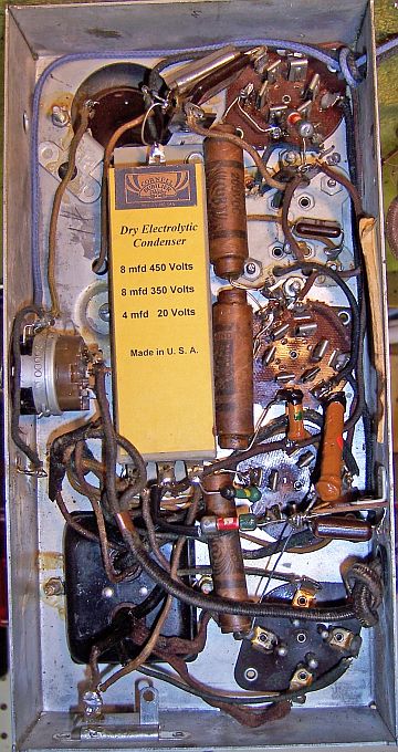
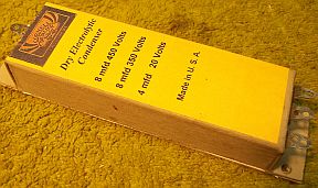
Filter Capacitor
The original dual filter capacitor had been removed and had been replaced by
three tubular
units under the chassis.
I formed a cardboard case using thin
cardboard from the back of a writing tablet. Two 10mfd 450 volt electrolytics
and a 22mfd 50 volt capacitor were
mounted inside, and their wire leads connected to ground lug
terminals mounted on one end. The ground connection (C-16 positive end) was mounted on
the opposite end of the capacitor box.
The cardboard case was assembled using carpenters wood
glue and various clamps. The finished case was then painted using gray
spray enamel. A label was fabricated using the correct original values. The Cornell Dubilier brand and logo was used, since several original
capacitors were CD brand Here is the result:
Wiring
The original line cord and plug were reused. The antenna and ground
leads were replaced using cloth covered stranded wire.
Tubes
All of the original tubes were reinstalled, since three of the four may have
been original. The grid cap on one of the 57 tubes was properly secured
using epoxy, followed by re-soldering the cap connection to the tube.
Cabinet
The cabinet only needed a good vacuuming inside and then cleaning on the
outside with GoJo and 00 steel wool. It turned out definitely
presentable without refinishing.
Testing and Alignment
Once the radio chassis was reassembled and the tubes and tube shields installed, power was brought up
slowly using a variac. AC power consumption was monitored using a watt meter, and a
DVM monitored the B+. The radio powered up and worked immediately.
The radio was then aligned. The regeneration control was left in the
maximum gain position, since the radio was stable when tuned across the
dial. The replacement volume control worked well and provided smooth
control of volume, even though it had the wrong taper.
Restoration Results
I was able to successfully reverse most previous repairs and restore the
likely original appearance of the radio under the chassis. Of course, I
did not know the exact appearance of some of the original parts. The
reproduction filter capacitor was the correct size, but coloring, labeling
and terminal type and configuration was just a guess. Exact placement of components and wiring
was also unknown, but there were some clues such as some original component lead lengths. The
existing volume control (replaced) was left in place.
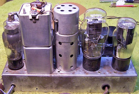
Chassis Bottom Before and After Restoration