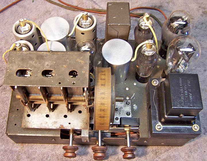
Zenith Model 230 Zenette Restoration
 |
The USA stock market crash of 1929 and the following Great Depression
resulted in a market mismatch with Zenith's early 1930's line of expensive radios.
So Zenith developed a low cost product line in order
to better match market needs. In order to distinguish those radios from their
high-end line, they branded them "Zenette" rather than
Zenith. Although supposedly a lower-end radio, the build quality of my
radio is very high.
The
circuit is an 8-tube superheterodyne that receives only the
broadcast band. It features a tuned RF amplifier and separate
oscillator and mixer stages and a separate AVC tube (unusual for early
1930's sets). It uses 2.5 volt tubes, typical of the early
1930's.
The radio had seen some servicing in the past but had not been hacked excessively.
This being the case, I
decided to try and retain the original top and bottom chassis appearance if
possible.
The schematic and a partial parts list for the radio can be found on Nostalgia
Air. |
My
antique radio restoration logs
Comparison to my Zenette 216-2
I had previously restored a Zenith
Model 216-2 Zenette (the "-2" indicates a 25hz model). The model 230 Zenette is quite similar, but has 8
tubes and a more complex circuit (the RF, First Detector, Oscillator, and IF
amplifier stages are very similar). The 216-2 uses a conventional type 55
duplex-diode/triode as the second detector, AVC, and first audio
amplifier. The 230 uses a type 57 pentode as an anode bend or biased type
detector/amplifier, with a separate type 57 AVC amplifier tube. Due to the need for
additional voltages for the AVC tube, the 230 has TWO wirewound metal voltage divider
resistors (similar to the Muter Candohm type). The 230 power transformer
also has two separate
filament windings: one for the RF and IF tubes, and a separate supply for the
AVC tube, detector, and audio power amplifier tubes. The center taps of
these windings go to different reference points. The RF/IF center tap reference is to
the chassis ground. The AVC/detector/audio reference is to their cathode
potential (at C- potential). Perhaps this was to reduce hum?
I noticed little or no difference in
performance between the 7-tube 216-2 and 8-tube 230 for this all this additional complexity.
History
The radio was purchased at a Southeast antique radio swap meet
rather than being shipped from somewhere. The only clues I found were
service tags glued to several original Zenith tubes. Those tubes were
tested and noted as "fair" on August 8, 1935 and again on January 16,
1941. The service tag read:
Replace with TUNG-SOL radio tubes
Ben's Radio Service
Dial 4-0028 Free Inspection
721 S. Union
Des Moines, Iowa
So apparently the original owner lived in or near Des Moines, Iowa and
twice took advantage of a local radio shop's offer to inspect the radio and test
the tubes FREE (when I checked the tubes, they checked GOOD!)
Previous Servicing
-
The original filter capacitor block had been replaced
(fortunately the
metal cover remained).
-
One of the original Dubilier Cub paper-wax capacitors and one dogbone type
resistor had been replaced with more modern components (not recently - an
older repair).
-
The volume control and switch had been replaced (the
original was an Allen-Bradley BradleyStat type, in which the switch often
fails).
-
The original type 280
rectifier had been replaced by a type 80 (not Zenith).
-
All the remaining tubes were
Zenith branded and likely ORIGINALS (all had similar engraved bases, for
example "Zenith type Z-58").
The type 56 was a globe type.
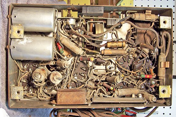
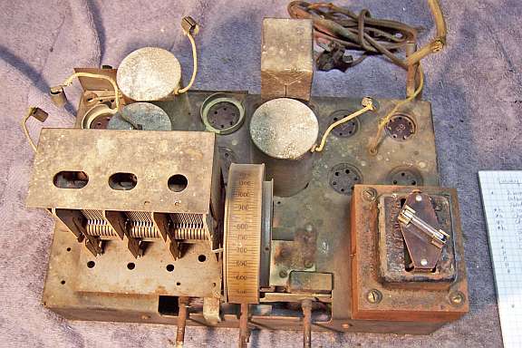
Chassis Before Restoration - VERY Dirty
Survey
My usual restoration procedure is to first make a complete
survey of the condition of all components. The survey results guide my
restoration strategy. If major and unique components are defective and
cannot be restored or replaced, I may elect to sell the radio rather than restore it.
I assume that all paper and electrolytic capacitors are leaky and thus should be
replaced (I always "restuff" the original components if possible).
And most original resistors would have drifted and be out of tolerance range.
-
The chassis was VERY dirty, and there was some surface rust.
There was considerable corrosion and pitting of the aluminum shield cans.
The power transformer covers and laminations were very rusty.
-
The dial drive cable was missing (a bronze wire type).
-
Two of the included knobs were incorrect.
-
The speaker cone was damaged.
-
The cabinet was in poor shape, with some loose joints and
missing veneer strips on the back of the arch.
-
The grille cloth had been replaced. The
grille cloth was glued to a solid piece of cardboard - no hole for
the speaker! My guess is that the seller did this so that the speaker
cone damage would not be noticed (light shining through the holes!).
-
The type 59 output tube was missing.
-
The power transformer was OK. It drew less than 10
watts unloaded, and all voltages were correct (the high voltage was balanced
on each side of the center tap).
-
The speaker field and output transformer were OK.
-
All RF coils were OK.
-
The input IF transformer had an open primary. The
output IF transformer was OK.
-
The original power cord was not safe and had several breaks.
The plug was OK, and an older style, but perhaps not original.
-
The speaker cable also had several breaks and the cloth
covering was worn away in spots. It appeared to be original, but I
noticed it had SIX leads (only 4 were used).
-
The tone and sensitivity controls were intermittent and
needed cleaning - they were BradleyStats, which are difficult to clean.
-
7 original dogbone type resistors were out of tolerance
by 30-100%.
-
The 6-tap metal clad lower voltage divider resistor (bias
divider) had one
section that was 40% high.
-
The 5-tap metal clad upper voltage divider resistor (B+ plate and screen
divider) changed values when the terminals were moved.
-
When the capacitor 22-175 (0.002mfd/600 volts) between the
plate and cathode of the AVC tube was removed, it was noted that a type
22-115 (.1mfd/200 volts) was installed. This was perhaps an error
during assembly - mistaking 22-115 for 22-175. This capacitor was
restuffed with a 0.0022mfd capacitor.
Cleaning
I normally clean the chassis before starting restoration.
I first blew off the above and below chassis dust with an air compressor.
The chassis was then partially disassembled for access and cleaning. The
tuning capacitor and dial drive mechanism was removed as a unit after
unsoldering the leads and ground braids. I had to remove the mixer coil shield cover in order to gain access to
the screws and spacers that held tuning capacitor shield to
chassis. The filter capacitor block cover was removed. The volume and tone controls and
their bracket were then removed after disconnecting all wiring from the
controls. It was very difficult to manipulate
the controls and bracket out of the chassis - there was no room to remove the
controls before removing the bracket, and the bracket could not be removed
without first removing the controls! So I had to loosen the control nuts,
leave the controls in place, and bend the bracket slightly in order to remove
it.
The very rusty power transformer was removed for wire brushing
and repainting. In order to gain access, I had to remove the 6-tap metal
resistor (bias divider) on the side of the chassis, which was riveted to the chassis.
This gave me a chance to "squeeze" the sides of the metal-clad
resistor unit in my large bench vise. This resulted in all resistances
being spot on and stable. Crimping the case on each side of the terminals
tends to restore the pressure of the contact bands on the resistance wire.
The bands will tend to loosen over time perhaps due to shrinkage of the
insulation material on which the resistance wire is wound, or gradual expansion
of the bands themselves. Both metal resistors were checked at 450 volts
for leakage using my Sprague TO-4 capacitor tester before being reinstalled in
the radio.
The chassis and top components were cleaned using GoJo, steel wool, and
toothbrushes. The tuning capacitor was removed from its shield cover and cleaned with soap,
water, and toothbrushes and then dried using a heat gun and lubricated.
The trimmer micas were removed prior to cleaning (I count the "turns to
tight" on each trimmer so that the trimmers can be returned to their
original position prior to alignment. The complex brass helical ring-and-pinion gear dial drive mechanism was removed, disassembled,
cleaned, and lubricated.
Repairs
The missing dial drive cable was replaced with
braided bronze cable. Fortunately, I had notes from my Zenith
216-2 restoration documenting how the cable was installed. I also
installed a suitable spring (I have a set of dial cable springs I purchased on
eBay.)
The power cord was replaced by new brown cloth covered wire and the original
plug (perhaps NOT original to the radio). The speaker cable was replaced
by a piece of 4-conductor brown cloth covered cable. A new rubber grommet
was installed for the speaker cable.
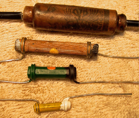
All paper capacitors (13) were rebuilt in their original cases
using modern 630 volt film capacitors in order to maintain the original
under-chassis appearance. The radio used Dubilier Cub type capacitors,
which are difficult to restuff. My process for restuffing Cub capacitors
is documented here.
All the Cub capacitors were originally marked with paint: either ORANGE (for .1mfd),
YELLOW (for .05mfd), or GREEN (for .5mfd). Cleaning the cardboard case
removed most of the paint. I suppose
this was to simplify assembly, since the person assembling the radio would not
have to read the label on the part! I did not repaint the capacitors since
some of the original paint did remain.
Main Filter Capacitor Block Replacement
I fabricated a replacement main filter block using two 10mfd/450 volt tubular
electrolytic capacitors. The original block was two 8mfd/500 volt
capacitors. There was evidence remaining that the original capacitor block
had terminal lugs (there were remains of the lugs on some of the wiring).
The "repairman" had simply cut the lugs from the original capacitor
and removed it. He then simply soldered the leads of the replacement
capacitor to the remnants of the lugs and taped over the splice. The
replacement was fabricated as follows:
- Cut a piece of insulation material (Fish Paper) to the pattern of the base of the outer metal
capacitor cover (so it would be largely hidden when the cover is in place).
Holes were then punched in the fish paper to correspond to the capacitor
cover mounting holes (using a leather punch).
- Cut a piece of hard rubber (1/8" thick) to fit inside the outer metal cover
(one could also use 1/8" or 1/4" plywood). Mine was salvaged
from a scrapped old battery set front panel.
- Sandwiched these two items together and drilled 4 holes at the corners for
6-32 hardware, spaced so that the ground lugs would not contact the chassis
or metal cover.
- Installed 4 ground lugs above and below, screwed together with 6-32 screws and nuts
- Installed 2 10uf 450 volt tubular caps on the top side, connected to the ground
lugs.
- Reattached the cover to the chassis. The retaining screws passed
through the Fish Paper thus holding the components in place.
- Reconnected the original wiring to the bottom ground lugs
The other filter capacitor, rated at 2mfd, was rebuilt in its original
cardboard case using a 4.7mfd/450 volt capacitor.
Dogbone Resistor Replacement
All original resistors more than 20% out of tolerance were replaced (there
were 10). I
used dogbone type resistors as were used originally. I picked out NOS and
used dogbone resistors from my stock and junk box that had drifted to the correct needed resistance and
then repainted them to match the original resistor's color codes. The
replacements may continue to drift, as would most new carbon composition type
resistors. But to me, maintaining the original look is more important than
long term reliability of the radio.
Volume and Tone Control Repairs
The volume, sensitivity and tone controls were of the Allen-Bradley BradleyStat type, which are
difficult to repair or clean. The original volume control had been
replaced. I found a used BradleyStat control in my junk box that was the
correct value (1 megohm), had a switch, and had the correct shaft length. But is was
a rheostat and not a potentiometer.
My process for restoring them is as follows:
- Grind down off the head of the brass rivet on the back that holds the center rear terminal and also
the back cover. Be careful not to damage the terminal, since it must be
reinstalled, and take off only the HEAD of the rivet and none of the shaft
(just enough to free the terminal lug).
- Remove the center terminal lug and the back cover of the control
- Remove the wiper - it can be pulled from its pivot (careful not to bend
it).
- Clean the wiper and resistance element with lacquer thinner on a Q-tip. Note
that the wiper does not directly contact resistance element, which is wound with
circles of wire. Use a minimum amount of lacquer thinner so as
not to damage the resistance element.
- Clean the switch contacts on the volume control (using lacquer thinner on
a Q-tip, Caig DeOxit, and finally 600 grit paper when all the above failed
to revive the contacts). Any sanding residue is then cleaned off
using lacquer thinner.
- Reinstall the wiper and test the control and power switch for
functionality
- Install the back cover
- Replace the center rear terminal lug on the rivet shaft, and then solder the terminal lug to the rivet to hold the back cover and terminal lug in place.
While opened for cleaning, the rheostat with switch was converted to a
potentiometer for the volume control by drilling a small hole in the bakelite
adjacent to an in contact with the end of the resistance element. A piece
of buss wire was then forced into the hole. A solder lug was attached to
the back cover of the control and the wire was connected to the solder lug.
Input IF Transformer Repair
The primary of the input IF transformer was open. The secondary was
OK. I removed the transformer from the radio for investigation. I
was hoping that the break would be on the OUTSIDE of the coil, so its leads were
disconnected and a few turns removed. I had no luck! No immediate
break was found. I then attached my DVM to the outer lead and probed the
coil with a sharp Exacto knife. I found continuity down about 2/3 of the
way, so it appeared that the break was on the INSIDE. At this point I
removed the coil assembly from the transformer (after carefully documenting
where each lead went). Using a heat gun, I was able to remove the primary
coil from its cardboard tube. I then started removing turns from the
INSIDE of the coil. A break was found almost immediately. I then
fished out another turn using my Exacto knife and continued removing
turns. Another break was found. But again, no continuity! This
was repeated several times with no luck. At this point I figured I would
have to remove too many turns to be able to use the coil (it would likely NOT be
adjustable to the IF frequency).
I replaced the cardboard coil form and its two coils using a similar assembly
from a 175KC modern IF transformer. The original trimmers were 70-160 pfd,
and the donor trimmers were 20-200 pfd. So hopefully I would be able to
properly align the transformer (confirmed!)
The frayed grid lead was replaced while the transformer was open.
5-Tap Voltage Divider Repair
Both metal clad wirewound multi-tap resistor units
were removed from the radio and their cases "squeezed" in my large
bench vise (on both sides of the terminals). The result was that
both units were now mechanically stable, had no leakage to ground, and all
values were almost spot on! However it was later noticed that the
remaining insulation material on the 5-tap unit was breaking off, likely due
to heat and age. This meant that there was now only about a half
millimeter gap between some of the lugs (at B+ potential) and ground! It was decided to replace the
upper 5-tap voltage divider with individual resistors. The lower 6-tap
divider was left in place, since it is a bias divider, has only about 70 volts across it, and if it fails would not result in catastrophic damage to
the radio.
A replacement was fabricated using a piece of insulating material salvaged
from an old Tektronics 'scope, solder lugs attached with 6-32 nuts and bolts,
and individual wirewound resistors. The Zenith data sheet for this part
listed the maximum dissipation of all resistors at 2 watts. So I used 5
watt wirewound units for most sections, and a 7-watt unit for the 3300 ohm
section (based on voltages listed in the schematic, the actual dissipation of
the 3300 ohm section was more like 3.5 watts!)
Other Repairs
- A type 59 and 280 tube were installed
- One grid lead was frayed. It was replaced (in order to do so I had
to remove the transformer shield)
Testing
After the radio was completely reassembled, power was applied through a
wattmeter and fused Variac. Power was brought up slowly while monitoring
the B+ voltage. Normal B+ was reached with only 100 volts applied, and the
radio worked. I assume that the high B+ was due to my using a 10mfd input
filter capacitor instead of the 8mfd originally used. While the B+
was correct, many of the other voltages were NOT correct. Also, I noticed
that the AVC voltage measured at the cold end of the RF and First Detector
coils was POSITIVE! This told me that the AVC amplifier stage was not
operating correctly. I then measured all the voltages with the following
results:
| Voltage Measured |
Spec |
Actual |
With Shunt |
| B+ High |
190 |
191.4 |
211.6 |
| 59 Output Screen |
165 |
161.7 |
178 |
| IF Amp Screen |
95 |
100 |
108 |
| Oscillator Screen |
70 |
22 ** |
23.7 |
| First Detector Cathode |
-2 |
-3 |
-2.2 |
| AVC Plate |
-65 |
-89 |
-65.5 |
| 59 Output Cathode |
-70 |
-92 |
-73 |
** Likely due to a design change - several resistors were not installed and
wiring slightly different from schematic.
So while the B+ voltages were close, the negative voltages were way off, even
though the bias divider values agreed closely with published Zenith
values. It appeared that the B- voltage was way to high. Not knowing
anything else to try, I tried shunting various resistors from B- to ground
(essentially in parallel with the bias divider) until the output tube cathode
voltage was correct (-70 volts). That turned out to be 4000 ohms (in
parallel with the 2405 ohm bias divider). All the remaining negative
voltages were now close to correct. The positive voltages were slightly
higher. The AVC tube was now operating correctly, delivering wide swings
of negative voltages to the RF and IF stages as stations were tuned. I
never figured out what was throwing the voltages off, and left the radio with
the 4000 ohm 5 watt resistor installed.
The radio was then aligned. It performs very well - it has excellent
sensitivity (due to the tuned RF stage) and good tone also.
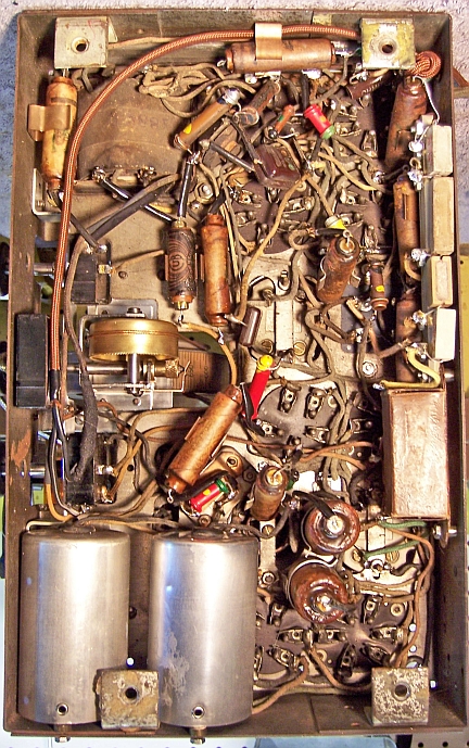
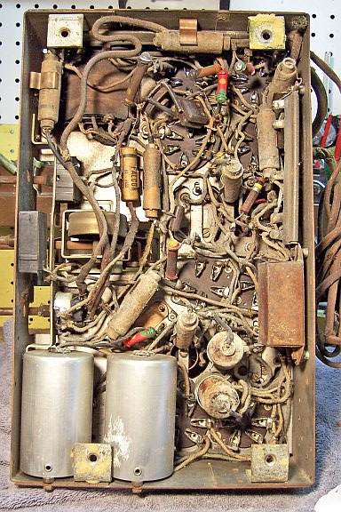
Restored Chassis
 |
 |
|
Restored Chassis |
Original Chassis |
