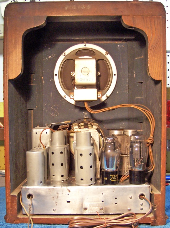
Zenith 5-S-29 (5S29) Restoration
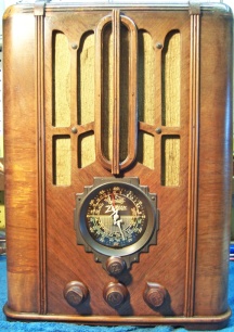 |
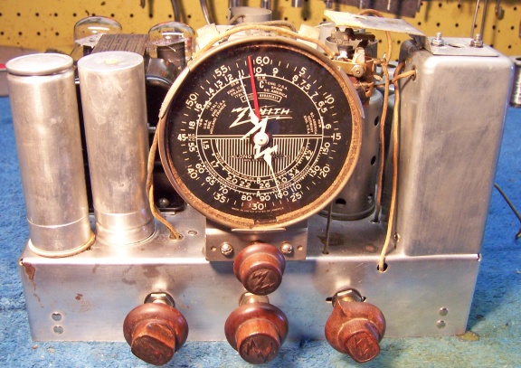
The Zenith 5-S-29 from 1936 is a 5-tube AC superhet circuit
radio in a fairly ornate tombstone (upright) cabinet. It has the smaller
"airplane" type dial with a "split second" hand which preceded
the larger black
dial sets in 1937. It receives the standard broadcast band and
two short wave bands. It features a tuned pre-selector for the
broadcast band (no RF amplifier, but has a three gang tuning capacitor).
The set had seen minimal servicing in the past. One of the filter
capacitors and a couple of wax/paper capacitors had been replaced. That being the case, I decided to try
to maintain the original top and bottom chassis appearance
and to reverse any previous repairs to the extent possible.
The schematic for the Zenith 5-S-29 can be found on Nostalgia
Air. Any part numbers will refer to numbers on that schematic. |
My
antique radio restoration logs
Overview
This radio was purchased at the 2012 Antique Wireless
Association conference and flea market in Charlotte, NC. It appeared to be
in original condition with its original knobs, grille cloth, and cabinet
finish. There were signs of prior servicing: one filter capacitor having
been replaced with a newer unit, metal tubes installed and two tube shields
removed, line cord replaced. The cabinet had some scratches, finish loss
and oxidation (foggy finish in places), but looked like
it would clean up and display well and not require refinishing. There were no signs of
an "electrical restoration" such as new wiring. The set was sold as not
working.
Previous Repairs
-
One original filter capacitor C13 had been replaced.
-
A couple of wax/paper capacitors had been replaced (C7,
C15).
-
All resistors appeared to be original.
-
It appeared that all tubes had been replaced. Metal
tubes had been installed for the 6A8, 6K7 and 6F6. The original tube
shields for the 6A8 and 6K7 had been removed. The 6B6 had been
replaced by a 6Q7G with its original shield (an acceptable substitute). In
1936, metal tubes (RCA) would work OK in Zeniths. Later Zenith (as
well as Philco) sets REQUIRED G type
glass tubes
used with shields, since pin 1 (the metal case of the tube) tube was
deliberately not grounded (in many cases, there was no pin 1 present at the
socket, preventing a service tech from grounding the pin and installing a
metal tube.) FYI, Philco went even further by using shield bases with small
holes which prevented using metal or even GT tubes!
-
The power cord
been replaced by a white vinyl cord with old style rectangular plug.
-
The chassis washers had been removed - likely deteriorated -
this meant that the control shafts and dial were not properly centered.
Survey
My usual restoration procedure is to first make a complete
survey of the condition of all components. The survey results guide my
restoration strategy. If major and unique components are defective or
missing and
cannot be restored or replaced, I may elect to sell the radio rather than restore it.
I always assume that all paper and electrolytic capacitors are leaky and thus should be
replaced (I always "restuff" the original containers if possible).
Any mica capacitors are assumed OK until testing proves otherwise.
-
The volume control and switch were OK.
-
The tone control pot was open.
-
The output transformer primary winding was open.
-
The speaker field and cone, power
transformer, and both IF transformers were good.
-
All of the RF coils were OK.
-
Four resistors had drifted and were now out of tolerance. All
were dogbone types.
-
The four section Candohm metal clad resistor R8 had one open section (the 85 ohm
section), but the other sections were close to correct values.
-
The tuning capacitor mounting grommets had deteriorated (typical).
-
Both pilot lamps were good
-
All chassis washers were missing.
Repairs
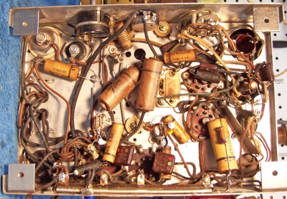
All tubes and shields were removed. Before starting repairs, I took photos of the chassis
top and bottom so that routing of wiring and component placement could be restored.
Lead dress is often critical in radios.
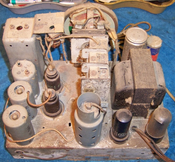
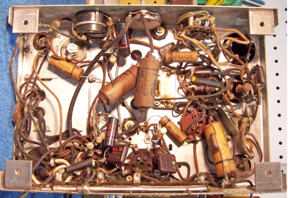
In Zenith schematics, all
resistors and capacitors having the same value have the same part number call
out. So for example, there may be multiple R2's or C4's on the schematic.
Before I start work on the chassis I annotate the schematic so that all parts
have unique identifiers. I usually add an alphabetic suffix, so that the
part numbers are thus R1A, R1B, etc. I then annotate the chassis photo with
these unique part numbers with a red felt-tip pen. I then removed all
non-original capacitors, documenting their locations
and connections. When I replace a component, I
always remove the original part completely from a terminal. Other
components connected at the terminal are protected from heat using old medical
clamps (hemostats). Excess solder is then removed using a solder sucker in order to
expose terminal holes for reattachment of the rebuilt or replaced component.
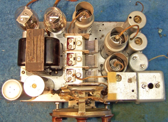
The top of the chassis was cleaned with GoJo hand cleaner and 00 steel
wool. Since this process may leave metal residue, I then went over the
chassis with a vacuum cleaner followed up by a small magnet and masking
tape. The tuning capacitor speed reduction mechanism was disassembled for
cleaning and lubrication. The tuning capacitor was cleaned in an old Heathkit ultrasonic
cleaner with dilute ammonia. After drying, the ball bearings were lubed with
distributor cam lubricant. The three tuning capacitor mounting grommets
were replaced using Philco GSm-Tuner grommets available from Renovated
Radios, with the small portion sliced off from the bottom side grommets using a single edge razor
blade (the upper grommets were left as is, since the projection sits in a small
indentation in the chassis). These grommets are not exactly perfect for
the application, since their center hole is slightly large, they are very
slightly too thick, and not firm enough. But they will work.
The missing chassis washers were replaced using CW2 washers available from Renovated
Radios. This washer left the knob shafts and dial centered properly.
Output Transformer
The original output transformer had an open primary winding. The
transformer was mounted on the speaker using simple bent-over tabs which fit
into slots in the speaker frame. No bolts were used. So the
replacement would have to have the same frame and tab width. Also, a bracket
was spot welded to the top of the transformer which held the terminal board where the
speaker cable was connected. At this point I was not sure it could be
removed without mangling it. I maintain a stock of (mostly used)
single-ended and push-pull output transformers. I examined my stock of
single-ended transformers and found a potential replacement. It was marked
"42 output transformer", which means it was originally used with a
type 42 tube (standard base version of the 6F6G used in this radio). The
ratio of the transformer was measured as 39.7:1. The voice coil of the
speaker measured 4.7 ohms DC, or about 5 ohms impedance. The 6F6 output
tube wants to see a load impedance of 7000 ohms. So the needed transformer
ratio is thus 37.4 (square root of 7000 divided by 5). So the turns ratio, DC
current and power ratings of the replacement transformer were acceptable. The core of the potential
replacement was VERY close to the size of the original. So I was able to
remove the original transformer core from its frame and substitute the core and
coil of the replacement. That way the replacement could be reinstalled on
the speaker and original terminal board bracket used. Other than
minor differences in lead routing, the replacement is not obvious!
Resistors and Capacitors
The four section Candohm resistor (R8) had one open section initially (the 85
ohm section), but most other sections were close to correct. I have found
that these metal clad resistors often respond favorably to clamping pressure
near their terminals when a section is unstable or has high resistance. I use
a small C-clamp and firm pressure on the metal housing on both sides near each terminal.
Thin wood or cardboard protects the chassis side of the clamp. Each terminal is simply a band around the resistance element, which is wound on
an insulator. Over time, the band expands or the insulator shrinks,
resulting in an unstable, high resistance, or sometimes an open section. In
this case, after squeezing, all sections were almost exactly correct and were
stable (resistance did not change when the terminal lug was moved)!
Compressing the metal case applies additional pressure from the band onto the
resistance element. There is some risk to this procedure, since the fish
paper insulation may be damaged in some cases, resulting in a short. For
this reason, many collectors never re-use a Candohm resistor in a restoration,
even when good! Instead, they remove the resistor and install terminal
strips and individual wire wound resistors. This of course greatly alters
the under-chassis appearance of the radio. I would also replace a Candohm
resistor, and especially if part of it was bad, if being PAID for a
restoration. But this radio will be a keeper (which will rarely if ever be
played).
The tone control measured open. It was removed from the radio for
examination. It turned out to be the non-repairable type, consisting of a
thin layer of carbon deposited on a cardboard form. A thin flexible metal plate contacted
the element. The rotating element applied pressure to the plate through an
insulator, so that the rotating arm did not directly contact the resistance
element. The element measured open, and cleaning simply removed the
carbon coating! So this control had to be replaced. It was replaced
by the correct IRC part (D13-123, 50K, audio taper) called for in the IRC manual
for this Zenith chassis. The D-type shaft that came with the control fit the
original knob. The shaft was cut to the correct length, and the original
star washer and nut was reinstalled.
All the original wax/paper capacitors were rebuilt in their original cases
using modern 630 volt film capacitors in order to maintain the original
under-chassis appearance. I reseal the cardboard tubes using rosin
salvaged from servicing RCA Radiola Superheterodyne catacombs (it melts at a low temperature and will not damage
the replacement capacitors). The set uses a mixture of capacitor
types including Zenith, Sprague and Cornel Dubilier. However, even though some capacitors are not branded Zenith, they all
had Zenith part numbers. Here
is how I restuff the Zenith and Sprague tubular capacitors. Here
is how I restuff Dubilier CUB capacitors. Two original wax/paper caps (C7 and C15) had been replaced in prior
servicing. I was able to find original Zenith capacitors in my parts stock
which had the correct values and part numbers that matched the
schematic. I collect Zenith and other branded paper capacitors for this
exact situation. These replacement capacitors were also rebuilt using new 630 volt film capacitors.
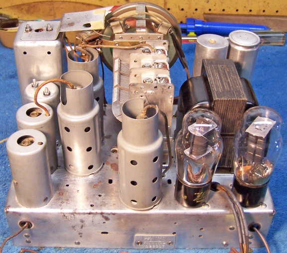
One of the original filter capacitors C13 and
was missing and had been
replaced in prior servicing. However, I had a screw base can type
capacitor in my parts stock which had the correct diameter and approximate
length. It also had a threaded stud for the positive terminal, which would
allow use of the existing original wiring (both original lugs were still in
place - one being simply soldered to the lugs of the replacement capacitor and
not cut off). One capacitor must be insulated
from the chassis, and the other is grounded. I moved the original
capacitor (which was originally grounded to the chassis) to the hole for the insulated capacitor (closest to the edge of the
chassis) since I had the appropriate insulating washers in stock that would fit
that capacitor. The replacement capacitor can was installed in the other hole.
I had not insulating washers that would fit that capacitor. The insulating
washers are not simple flat washers: they have a projection that fits in the
chassis hole to prevent the capacitor from contacting the chassis should it
move. These are generally obtained from parts chassis.
The original C13 and replacement (8 mfd, 440 volts) were both restuffed using 10mfd 450 volt capacitors. The cans were scored deeply
about 1" up from their base on my Unimat lathe, and then the cut was
completed using a
Exacto hobby razor saw. In the case of the original capacitor, the positive electrode
(foil) was removed, retaining the
stud. The stud was cut off short and a hole drilled for a screw, nut, and
solder lug. A plus lead of a 10mfd 450 electrolytic was connected to the solder
lug. The negative lead of the replacement capacitor, extended with bare
bus wire and with insulating
sleeving, was routed through a small hole drilled in the base near the mounting
threads. After the
capacitor was mounted, the negative lead was soldered to the a replacement
negative terminal (the original had been cut off). The original positive terminal was used.
The replacement capacitor was a "dry" type and did not have an
internal center
stud. Once its contents were removed and it was cleaned up, a small hole
was drilled next to the positive terminal threaded stud. The positive lead
of the replacement 10mfd capacitor was extended with 22 gauge bus wire and
routed through the hole. The existing original inside nut on the positive
lug was removed, the bus wire wrapped around the stud, and the nut
replaced. The negative lead of the replacement 10mfd capacitor was routed
through a small hole drilled in the base near the edge. This lead was
clamped between the capacitor body and the chassis when the capacitor was
mounted. Just in case, the lead was also clamped under a nearby power
transformer mounting nut.
All small resistors in the set were dogbone types, and most were 1/3 or 1/4 watt
size. Four were not in tolerance and would have to be replaced. In
order to maintain the under chassis appearance, I decided to use the same type
resistor to replace them. But of course, any replacement
dogbone resistors would also likely have drifted! I collect all the used and NOS dogbone
resistors I can find, and retain any out of tolerance dogbone resistors that I remove
from radios. I searched my 1/4 watt dogbone resistor stocks for resistors
which had the correct lead length and value within 15% or so. I then repaint these
resistors with the appropriate body-end-dot color code of the ORIGINAL resistor using
enamel hobby paint.
Wiring
The speaker cable had insulation breaks and had bare wire showing near the
chassis. But most of the cable was usable. The cable was repaired by
cutting each wire at the bare portion and installing two layers of shrink tubing
on each wire, one wire at a time. The same process was used to repair the pilot
lamp leads. For some reason, the original pilot lamp leads had been cut, spliced (not
soldered!) and insulated with tape. Since the dial drive belt had been
replaced, perhaps the front of the dial drive mechanism was removed in order to
install a replacement (a few wraps of twine!) But the pilot lamp sockets could
have simply been pulled off their mounting brackets in order to do
this!
During testing, it was discovered that the antenna lead was shorting out to
the antenna coil shield, where it passes through an eyeleted hole. It was
repaired by pulling the wire back through the hole, cutting off the bare and
damaged part, replacing the knot (strain relief) and reconnecting the lead to
the antenna coil.
The original power cord had already been replaced, so I had no idea what the
original looked like. But postings on Antique
Radio Forums indicated that 1936 Zeniths had standard flat brown rubber
(vinyl) cords with integral molded plugs (1935 and earlier had cloth covered
cords). So I installed a standard replacement brown vinyl cord with molded
plug.
All other wiring in the set was cloth covered and in excellent condition.
Other Repairs
The band switch was given a good spraying with GC Big Bath cleaner, which
leaves behind no residue. The dial drive speed
reducer was disassembled and its parts cleaned in my Heathkit ultrasonic cleaner
using dilute ammonia, followed by cleaning with soap, water, and toothbrushes.
Gear hubs were cleaned using a pipe cleaner. The mechanism was then
reassembled and oiled using Turbine oil. The dial drive belt was replaced
by a 2" diameter thin (about 1/16" thick) O-ring. The mechanism then worked
perfectly.
Testing and Alignment
Once the radio was reassembled and the tubes installed, power was brought up
slowly using a variac. AC power consumption was monitored using a watt meter, and a
DVM monitored the B+. The radio came alive immediately and worked. The set was then aligned. The
only problem found was that the pre-selector trimmer did not peak up properly
(it was left wide open). The
radio worked well and picked up lots of stations on all bands using only a 20' piece of wire
in my basement. The tone was very good, so the output transformer
replacement was successful.
Restoration Results - After Restoration
