RCA Model 110 Cathedral Restoration
My
antique radio restoration logs
|

|
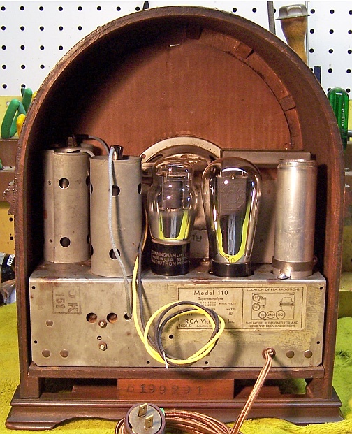
The RCA Model 110 is a 5-tube AC non-AVC superhet circuit
radio. It receives the standard broadcast band and the old police
call band. The circuit is somewhat unusual, in that it has an RF
amplifier stage but no IF amplifier stage. The schematic can be found
on-line at Nostalgia
Air. Any part numbers will refer to numbers on that schematic. |
Condition As Found
The radio was purchased on eBay. It was described as working with its
original parts (I was skeptical)! I downloaded the photos in eBay and enlarged
them as much as possible. It did indeed appear that most if not all original
parts were still present, although I did see some tacked-in filter
capacitors. When the radio arrived, I confirmed that all the original
parts were present. No parts had been replaced, but several filter
capacitors had been disconnected and newer tubular capacitors installed.
It appeared that the radio had been serviced multiple times, since there were
several generations of replacement filter capacitors present. Once it was
determined that there were no B+ shorts, I slowly powered up the radio using a
fused variac and watt meter, with a DVM monitoring B+. One resistor had
broken loose from the volume control, and the antenna lead had broken off from
the antenna coil. Once these were repaired, the radio did indeed work as
advertised! This is truly amazing on original parts (one of three filter
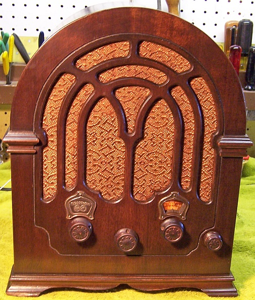
capacitors was original). The cabinet was
in great original condition, as were the knobs and grille cloth. The power
cord had been replaced by a newer cloth covered type. All of the grid cap
leads had been replaced with new wire (correct cloth covered type). From
prior experience with this vintage GE/RCA, most of the original grid cap leads
were rubber covered and the insulation would be flaking off, resulting in shorts to the
tube shields.
I decided to try to reverse any previous servicing to the extent possible
and to restore as much of the original top and bottom
chassis appearance as possible. My objective was that any repairs or
restoration would not be obvious, and no new parts visible. The objective
was NOT to return the radio to factory new condition! This same chassis is used in several RCA and GE radios.
I had previously restored a very similar chassis, the RCA
R-28P. But that radio had seen extensive servicing and many original
parts had been removed. This one was largely original.
Survey
My usual restoration procedure is to first make a complete
survey of the condition of all components. The survey results guide my
restoration strategy. If major and unique components are defective and
cannot be restored, I may elect to sell the radio rather than restore it.
I assume that all paper and electrolytic capacitors are leaky and thus should be
replaced (I always "restuff" the original containers if possible).
Since this radio actually worked, it was assumed that all major parts were OK. I
did check the power transformer for balanced high voltage across the center tap
and wattage draw with no load. It was OK, even though there were signs of
tar or wax leakage on the chassis. This was likely due to overheating and
high current draw due to leaky capacitors in the past.
-
One original tube shield had been replaced by one that did
not properly fit. Luckily, I actually found a correct original shield
in my junk box!
-
The volume control (a 4.5K wire-wound control with switch) was
open at some point. A common failure mode of these controls, which use
several sections of different size resistance wire, is a break between
sections due to failed welds or other methods of joining the nichrome wires.
-
The power switch (on the volume control) measured high
resistance - likely due to dirt and corrosion.
-
The tubes were stated as tested and replaced as
needed. All tubes tested strong, except for the 2A7 which tested weak
(but did work).
-
Six resistors were out of tolerance. All were old style
"dogbone" resistors in various sizes.
Repairs
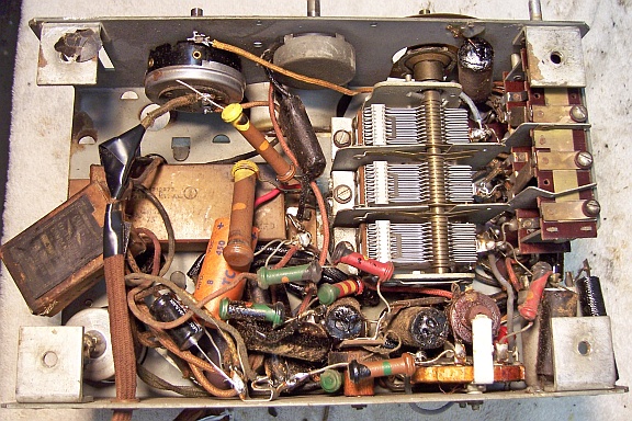
The chassis is very compact and there is really no way to service many of the
components without removing others for access. Here is what the chassis
looked like before the start of restoration. The loose 14K resistor is
supposed to be connected to the volume control rheostat:
First, all non-original parts were removed after taking careful notes of where they connected.
Several parts that originally had been connected to one lug of the two-section
filter capacitor were moved back in the vicinity of the lug (as found, they were
hanging in mid air and connected to tacked in filter capacitors). I
then took more photos of the chassis, since this would likely represent the
original condition prior to servicing. In order to gain access to the capacitors and resistors that needed
replacement, I removed the tuning capacitor, the volume and tone controls, the
speaker (chassis top), the filter capacitors, the detector plate
choke L9, and the
antenna and RF coils (on top of the chassis, L1-L4). One must be VERY
careful with the speaker leads, which are sleeved and quite stiff. They
are easily damaged, and a tight fit through a hole in the chassis which has no
grommet.
Capacitors
All paper capacitors were rebuilt
using modern 630 volt axial film capacitors in order to maintain the original
under-chassis appearance. There were two types of paper capacitors used in
this radio: the first type was a cardboard tube containing the paper-foil roll
with its ends sealed with tar (not wax). These are very easy to
restuff. First the component leads are pulled out of each end, which also takes much
of the tar with them. Then the foil roll is pushed out one end using a
screwdriver. The cardboard tube is then cleaned of any remaining tar. I also clean the outside of the tube by heating with a heat gun and
wiping away the wax, tar, and dirt. A new axial film capacitor is then
inserted. Before restuffing, the
component's original lead length and any insulating sleeving use is noted. In
some cases longer leads must be first attached to the replacement capacitor
before restuffing (I use #20 or #22 solid tinned bus wire to extend the leads).Here is the method I use
to rebuild cardboard tube type capacitors.
The other type of paper capacitor used in this radio has no cardboard
tube. These look like a block of tar wrapped in a thin fish paper wrapper, and
are generally oblong in shape rather than round. I came up with a way to restuff (more correctly
to reproduce) these RCA capacitors. See Restuffing
Early 1930's RCA Paper Capacitors. The tone control and quality
capacitor C20 and C30 was this type, and contained two capacitors (.035 and
.005mfd).
It was reconstructed using a .0047mfd (the quality capacitor) and a .015mfd
and .022mfd capacitor in parallel (the tone control capacitor). Two
capacitors in parallel were used because a .033mfd was too thick, and because
of the shape of the original capacitor. The original outer fish paper wrapper
(complete with part number) was reattached using hot glue. Capacitor C13 (2400pf) appeared to
be a paper capacitor rather than mica. It was in a very difficult position
to remove it (under the band switch), and would be difficult to reproduce. I disconnected one end
and measured leakage and capacitance. Leakage measured more than 40
megohms DC (infinity) on my DVM, but the capacitance measured 4200pf using my DVM's capacitor measurement
function (a higher reading usually indicates a leaky capacitor). Since it was shunted by a 20K
resistor and was only exposed to low voltages, I left it in place.
The wet can type electrolytic capacitor C21 was rebuilt in its
original can. The original was 10mfd, voltage unknown. The can was deeply scored about 1" up from the base
using my small Unimat lathe and the cut completed using a hobby razor saw. In
this case, it was completely dry - with no electrolyte inside (otherwise, the process
can get messy!) This
cut would be hidden by the capacitor's mounting clamp. The original
contents were removed (positive electrode foil and insulation sleeve) and the case
was cleaned. The positive center stud was cut short and a hole drilled in
the end in order to attach a ground lug using 4-40 hardware. The positive
terminal of the 10mfd/450 volt replacement capacitor was soldered to the ground
lug. The negative lead of the replacement capacitor was extended, insulated with spaghetti tubing, and
routed through a hole drilled into the side of the capacitor. The negative
lead would eventually be clamped between the capacitor can and the mounting
clamp and thus hidden. The two halves of the can were joined using 1" PVC plumbing couplings and
epoxy cement. I also apply a few layers of masking tape to the PVC coupling to
take up excess clearance with the can. The original mounting clamp
was very rusty. It was removed from the chassis by drilling out two
rivets. It was then cleaned up using wire brushes on my bench grinder and
using a Dremel tool with a small wire brush. It was then reattached to the
chassis using 6-32x1/4" hardware. The negative lead of the capacitor
(hidden by the top of the clamp) was routed through the capacitor mounting hole
and clamped under one of the mounting nuts to ensure a good ground connection.
The cardboard cased block capacitor C22/C23 (2 x 4mfd at 300 and 150 volts) was opened up and
restuffed using two 4.7mfd/450 volt electrolytic capacitors. First the
backs of the three hollow rivets were ground off using a Dremel Mototool with a
grinding stone. The rivets could then be removed from the top with minimum
damage to the cardboard case, and could be reattached later. The stiff bottom cardboard
base was then removed using a
heat gun to melt the glue and wax. The capacitor case was then carefully
opened, again using the heat gun. The capacitor inside was then removed
after severing the foil connections to the back of the external terminal rivets. Excess foil
was then removed from around the terminals from the inside using a sharp Exact
knife and #11 blade. Small holes were
then drilled through the center of the rivets holding the terminals and through
the cardboard on the back side. Two 4.7mfd at 450 volt capacitors were
then mounted inside, and their positive leads were routed through the drilled
holes. The leads were then wrapped around the terminals on the front side
and soldered. The negative leads of both capacitors were joined to a piece
of bare bus wire, which was insulated using small spaghetti tubing, routed
through the drilled hole in the common external lug, wrapped around the base of
the lug and soldered. The capacitor was then reassembled and held together
using hot glue. The bottom cardboard base was reattached using hot
glue. The three rivets were then reinstalled. Two are held in place
by the capacitor's mounting screws. The one that did not have a mounting screw to hold
it in place was secured using a small dab of epoxy.
Here are the
restuffed filter capacitors:

All the mica capacitors were left alone. Any of these that could be
tested by lifting one lead (in the process of replacing another part) were
tested. All that I tested were good.
Resistors
All original resistors significantly more than 20% out of tolerance were replaced. I
used dogbone type resistors as were used originally. I purchase all the NOS
and used dogbone resistors I can find on eBay or at antique radio swap
meets. I picked out NOS and used
dogbone resistors from my collection that were either in tolerance or had drifted to the correct needed resistance and then repainted them to
match the original resistor's color codes using hobby enamel paint. The replacements may continue to drift, as would most new carbon
composition type resistors. But to me, maintaining the original look is
more important than long term reliability of the radio. And besides, most
modern collectors would simply rip out all the vintage parts and replace them
with new parts without even testing them!
 |
Here are the replacement dog-bone
resistors, ready for installation in the radio. Three are NOS or used parts that are still in tolerance (the 60K, 1 Meg, and 20K). The other two
have been repainted using hobby paint. The NOS 14K 1 watt resistor was
originally a NOS 10K, but now measures 14.03K. The 200K 1/2 watt was originally
100K but now measures 186K.
|
Volume Control
The volume control was intermittent in operation (the resistance jumped around) and measured open circuit at some
point of rotation. I originally suspected a break in the resistance wire -
a common failure mode. The control was removed from the radio and was disassembled. It was found that there was no break in the resistance
wire - apparently the control only needed cleaning! The C-clip retaining
the shaft was removed and the shaft and wiper removed. All parts were then
cleaned using lacquer thinner. A Q-Tip and lacquer thinner was used to clean the resistance
wire contact area. The wiper showed some wear and corrosion. The
contact area was smoothed using 600 grit emery paper and then cleaned using
lacquer thinner. Upon reassembly, the control operated smoothly throughout its
range. The resistance measured 5.6K ohms rather than the specified 4.5K
ohms. The minimum resistance was 115 ohms (not specified in the Riders
documentation). The control was marked "RCA-VICTOR CO." so it
must have been original.
Other Repairs
- The tuning capacitor rubber grommets were replaced using standard AES
P-G038 rubber grommets which worked perfectly, although they were likely stiffer than the
original parts.
- The chassis was cleaned using GoJo and steel wool, tooth brushes, small
bottle brushes, and pipe cleaners. Since use of steel wool may leave
behind conductive fibers, I then went over the chassis with small magnets, a
vacuum cleaner, and masking tape.
- The band switch was cleaned using lacquer thinner, Big Bath spray cleaner,
and finally Caig DeOxit D5. Contact resistance was tested prior to
reassembly of the radio.
- The line cord was replaced with a new reproduction cloth covered cord and
old style plug. The cloth covered cord that came with the radio was
much too thick.
- The original 80 shouldered or ST style rectifier was replaced. In the radio,
the rectifier socket is recessed. I assume this is to allow room for a
globe type 280 rectifier, which I installed. The globe style tube looks more correct
than a ST type tube. 1933 was about the time that globe type tubes
were being phased out. It is not known which type was originally
installed.
- The original rubber covered grid cap leads had already been replaced, and the
remaining original wiring was OK. Insulating sleeving was installed on
each grid cap lead to prevent shorting to the tube shield.
- The original ground lead had been cut short, and the antenna lead had been
replaced. Both were replaced using cloth covered wire of the correct
color, and were knotted around the antenna coil bracket as shown in the
schematic.
Testing and Alignment
Once the radio was reassembled and tubes installed, power was brought up
slowly using a variac. AC power was monitored using a watt meter, and a
DVM monitored the B+. The radio came alive immediately and worked. Warm-up
is slow, likely due to a weak 2A7 first detector tube.
The set was aligned - no surprises. It picked up lots of stations
using my basement 50' antenna. It even picked up some stations on the "police" band
in the middle of the day (including the local low-power traffic station at 1610.
Tone was OK, but there was some distortion which is characteristic of the type
of second detector used.
Restoration Results
I was able to successfully reverse previous repairs and to restore the radio
to its unserviced appearance. No replacement parts are visible except for the power cord, grid cap leads, and the antenna and ground
leads. It is likely that some of the components were not in exactly the
same position as installed at the factory, since the radio had already been
serviced when I received it. And there is a slight difference in
appearance between the tar originally used to seal the paper capacitors and the
rosin that I used.
|
Before Restoration (Non-Original Parts Removed |
After Restoration |
 |
 |